LG LAC6700R User manual
CAR CD/MP3/WMA Receiver
OWNER’S MANUAL
MODEL : LAC6700R
LAC6700R_ENG
Please read this instruction booklet carefully
and completely before installing, operating
or adjusting this product.
Safety note
2
The lightning flash with the arrowhead symbol, within an equilateral
triangle is intended to alert the user about the presence of uninsulated
dangerous voltage within the product’s enclosure that may be of
sufficient magnitude to constitute a risk of electric shock.
The exclamation point within an equilateral triangle is intended to alert the
user to the presence of important operating and maintenance (servicing)
instructions in the literature accompanying the appliance.
Always operate the vehicle in a safe manner.
Do not become distracted by the vehicle while driving, and always be fully
aware of all driving condition. Do not change settings, or any functions.
Pull over in a safe and legal manner before attempting such operations.
Do not use for many hours at extremely low or high temperature.
(-10~60°C)
To reduce the risk of electric shock, do not remove the cover or back of
this product. There are no user-serviceable parts inside.
Refer servicing to qualified service personnel.
To reduce the risk of fire or electric shock, do not expose this product to
dripping or splashing water, rain, or moisture.
The temperature of unit’s outside can be extremely high, please use the
unit after proper installation in your vehicle.
CAUTION : This product uses a Laser System.
To ensure proper use of this product, please read this owner’s manual carefully
and retain it for future reference. Should the unit require maintenance, contact an
authorized service center.
Performing controls, adjustments, or carrying out procedures other than those
specified herein may result in hazardous radiation exposure.
To prevent direct exposure to laser beam, do not try to open the enclosure.
Visible laser radiation when open. DO NOT STARE INTO BEAM.
CAUTION : TO REDUCE THE RISK OF ELECTRIC
SHOCK DO NOT SPLIT COVER(OR BACK) NO USER
SERVICEABLE PARTS INSIDE. REFER SERVICING
TO QUALIFIED SERVICE PERSONNEL.
CAUTION
RISK OF ELECTRIC SHOCK
DO NOT OPEN
Safety note
3
8 cm
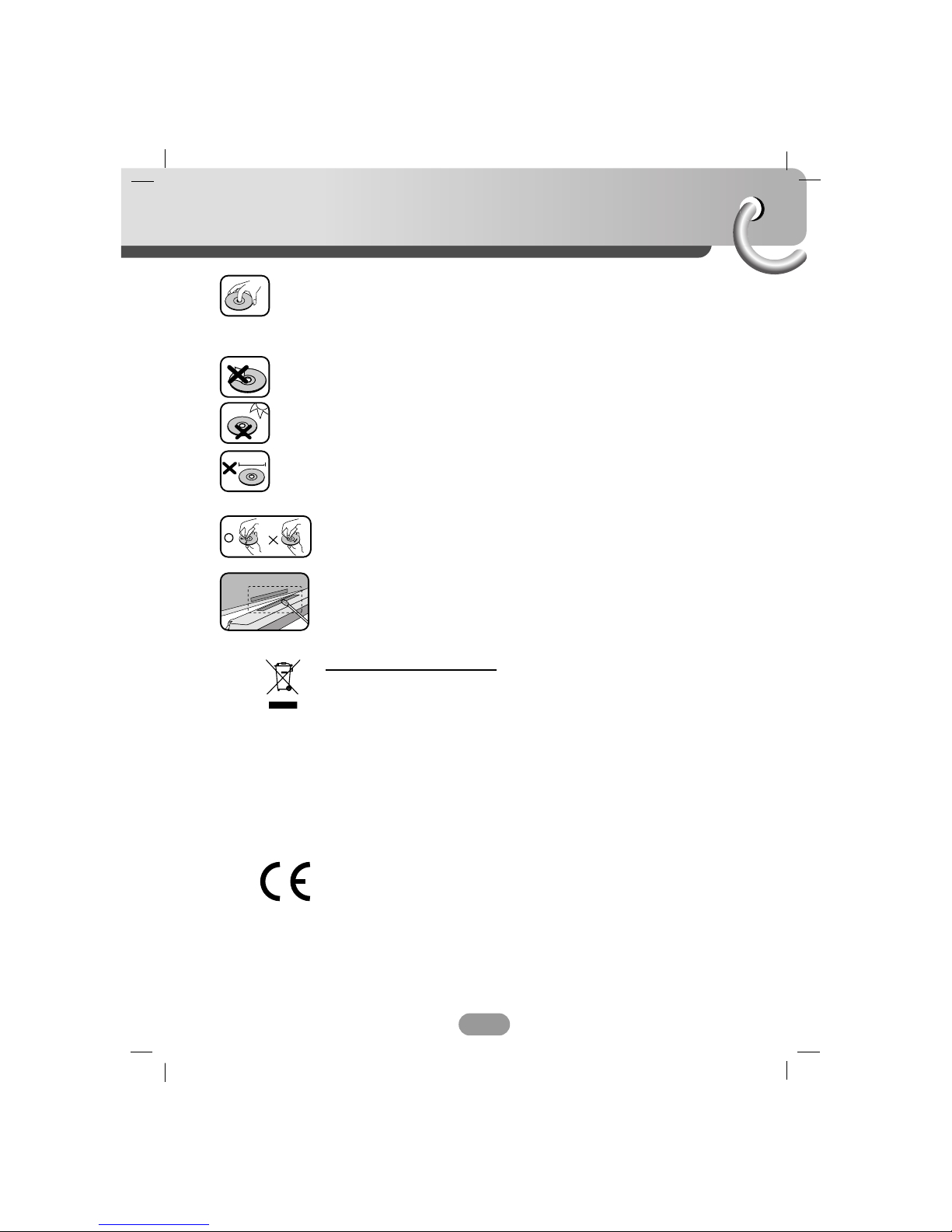
• A defective or soiled disc inserted into unit can cause sound to drop out
during playback.
• Handle the disc by holding its inner and outer edges.
• Do not touch the surface of the unlabeled side of the disc.
Do not stick paper or tape etc. on the surface.
Do not expose the disc to direct sunlight or excessive heat.
This unit cannot play 8cm disc (use 12cm disc only).
• Clean the disc before playback. Wipe the disc from the center outward
with a cleaning cloth.
• Never use solvents such as benzine or alcohol to clean the disc.
Periodically wipe the contacts on the back of the control panel with a
cotton swap moistened with alcohol.
Disposal of your old appliance
1. When this crossed-out wheeled bin symbol is attached to a product, it means
the product is covered by the European Directive 2002/96/EC.
2. All electrical and electronic products should be disposed of separately from the
municipal waste stream via designated collection facilities appointed by the
government or the local authorities.
3. The correct disposal of your old appliance will help prevent potential negative
consequences for the environment and human health.
4. For more detailed information about disposal of your old appliance, please
contact your city office, waste disposal service or the shop where you pur-
chased the product.
This product is manufactured to comply with Directive 2005/83/EEC(ANNEX I ,
3.2.9), 72/245/EEC and 2006/95/EEC.

Table of contents
4
Safety note . . . . . . . . . . . . . . . . . . . . . . . . . . . . . . . . . . . . . . . . . . . .2-3
Table of contents . . . . . . . . . . . . . . . . . . . . . . . . . . . . . . . . . . . . . . . . .4
Before use . . . . . . . . . . . . . . . . . . . . . . . . . . . . . . . . . . . . . . . . . . . . .5
Control panel . . . . . . . . . . . . . . . . . . . . . . . . . . . . . . . . . . . . . . . . . . . .6
Remote control . . . . . . . . . . . . . . . . . . . . . . . . . . . . . . . . . . . . . . . . . .7
Installation . . . . . . . . . . . . . . . . . . . . . . . . . . . . . . . . . . . . . . . . . . . . . .8
Connection diagram . . . . . . . . . . . . . . . . . . . . . . . . . . . . . . . . . . . . . . .9
Connection . . . . . . . . . . . . . . . . . . . . . . . . . . . . . . . . . . . . . . . . . . . . .10
Basic operation . . . . . . . . . . . . . . . . . . . . . . . . . . . . . . . . . . . . . . . 11-14
Radio operation . . . . . . . . . . . . . . . . . . . . . . . . . . . . . . . . . . . . . . . . . 15
RDS operation . . . . . . . . . . . . . . . . . . . . . . . . . . . . . . . . . . . . . . . . . . 16
CD/MP3/WMA operation . . . . . . . . . . . . . . . . . . . . . . . . . . . . . . . . 17-18
USB operation . . . . . . . . . . . . . . . . . . . . . . . . . . . . . . . . . . . . . . . . . . 19
Troubleshooting . . . . . . . . . . . . . . . . . . . . . . . . . . . . . . . . . . . . . . . . 20
Specifications . . . . . . . . . . . . . . . . . . . . . . . . . . . . . . . . . . . . . . . . . . 21
A section whose title has one of the following symbols is applicable only to
the disc represented by the symbol.
Audio CDs
MP3 files
WMA files
WMA
MP3
CD
Before use
5
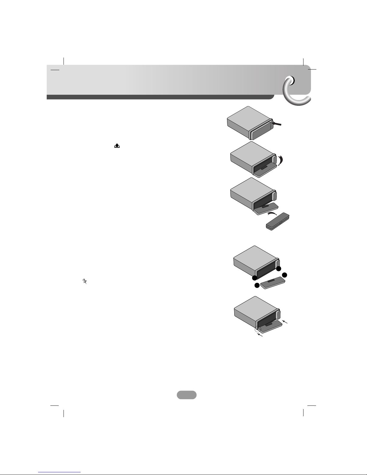
Detaching the control panel
You can detach the control panel when leaving the car.
When detaching or attaching the control panel, be careful not
to damage the connectors on the back of the control panel
and on the panel holder.
1. Press the “ ” button to unlock the control panel.
2. Push the control panel to left
3. Pull the control panel out of the unit.
4. Put the detached control panel into the protective case.
Attachable control panel
1 Attach part Aof the control panel to part Bof the unit.
2 Attach part Cof the control panel to part Dof the unit
while pushing the control panel to left.
3 Close the front panel.
Caution
• When detaching or attaching the control panel, do not press
the display or control buttons.
• The control buttons may not work properly if the control
panel is not attached properly. If this occurs, gently press the
control panel.
• Do not leave the control panel in any area exposed to high
temperatures or direct sunlight.
• Do not drop the control panel or otherwise subject it to strong
impact.
• Do not allow such volatile agents as benzine, thinner, or
insecticides to come into contact with the surface of the
control panel.
• Do not try to disassemble the control panel.
A
B
D
C
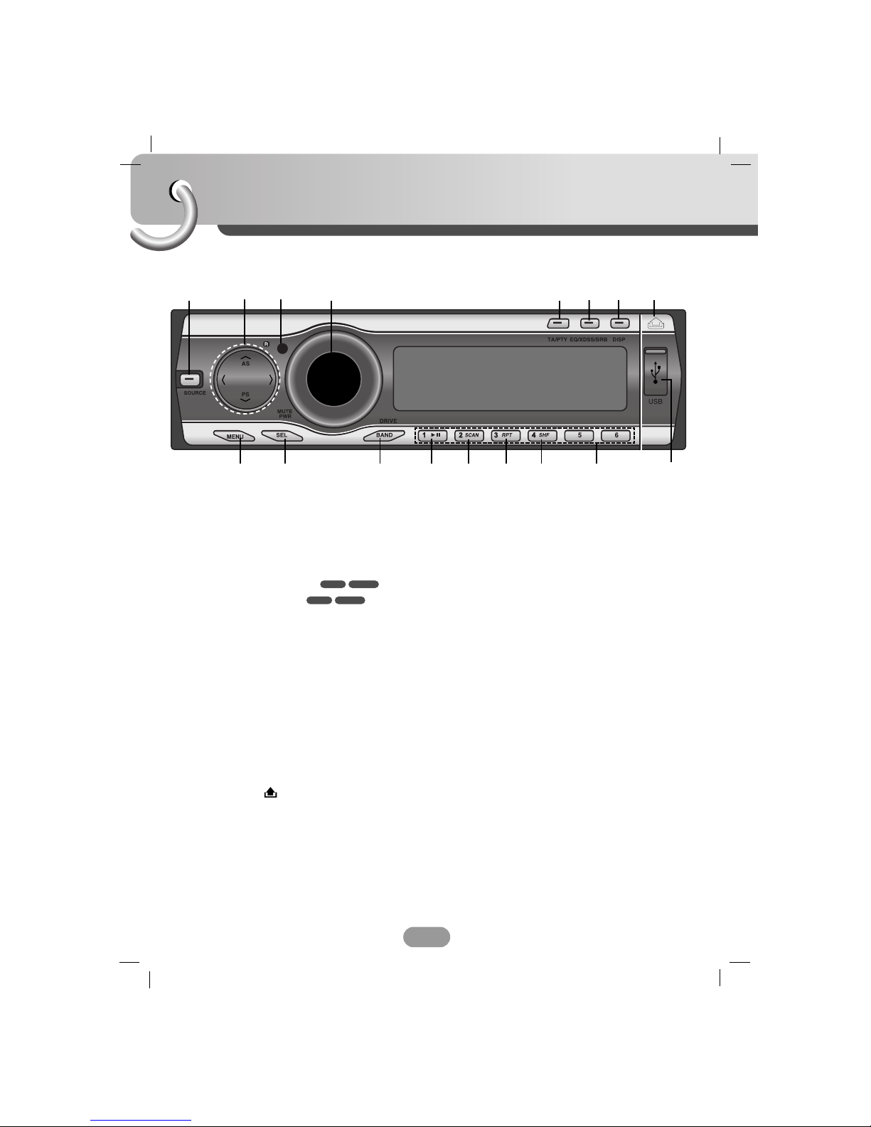
Control Panel
6
1[SOURCE]
2• Skip / Search II/ii
• Seek/ Tune II/ii
• Auto Store [UU/AS]
• Preset Scan [uu/PS]
• MP3 Track +10/-10 UU/uu
• Folder Up/Down UU/uu
3Remote Sensor
4• Volume
• [MUTE]
• Power [PWR]
5• Traffic Announcement [TA]
• Programme Type [PTY]
6• Equalizer [EQ]
• Extreme Dynamic Sound System
[XDSS]
• Bass Reverb Blaster [BRB]
7Display [DISP]
8Release/Eject
9USB Slot
10 Preset Station [1~6]
11 Shuffle [SHF]
12 Repeat [RPT]
13 Intro Scan [SCAN]
14 Play/Pause B/X
15 • [BAND]
• [DRIVE]
16 Select [SEL]
17 [MENU]
WMAMP3
WMAMP3
12 4 67
9
15
3
17 14 13 12 11 10
8
16
5
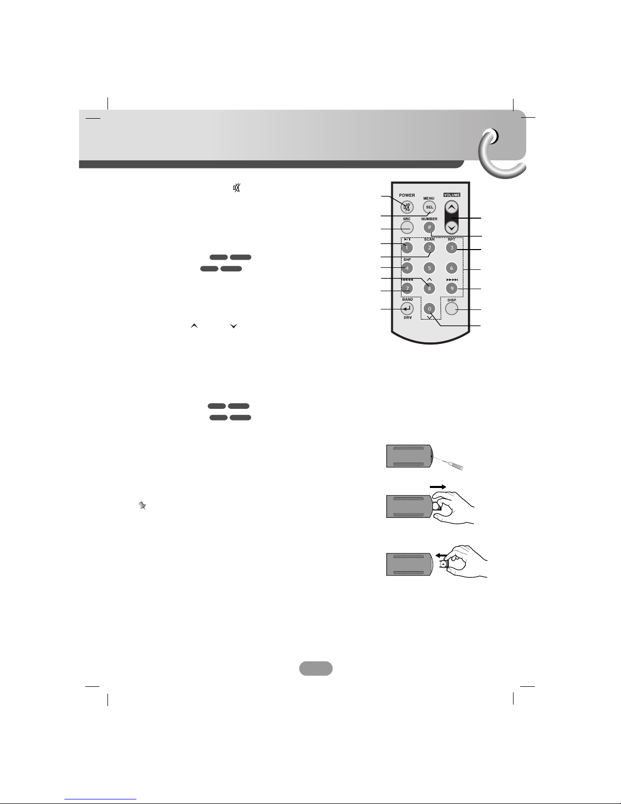
Remote control
7
Battery installation
1 Remove the battery holder with a sharp product like a ball
point pen.
2 Install the battery on the battery holder.
3 Install the battery holder back into its original position.
Note
• Use only one CR2025 (3V) lithium battery.
• Remove the battery if the remote control is not used for a
long period of time.
• Do not leave the product in a hot or humid place.
• Do not handle the battery with metallic tools.
• Do not store the battery with metallic materials.
1Power [POWER] / Mute
2Select [MENU/SEL]
3Source [SRC]
4Play / Pause B/X
5Intro Scan [SCAN]
6Shuffle [SHF]
7• MP3 Track +10
• Folder Up UU
8• CD Skip / Search ?m m
• Seek / Tune ?m m
9• [BAND]
• DRIVE [DRV]
10 Volume Up / Down
11 Number [#]
12 Repeat [RPT]
13 Number [0 -9]
14 • CD Skip / Search M M?
• Seek / Tune M M?
15 Display [DISP.]
16 • MP3 Track -10
• Folder Down uuWMAMP3
WMAMP3
WMAMP3
WMAMP3
10
12
14
15
16
1
3
8
9
4
5
2
6
7
11
13
A
A
Installation
8
5
4
3
1
2
6
Bend the claws
according to
the thickness
of the
dashboard
Control panel
Control panel
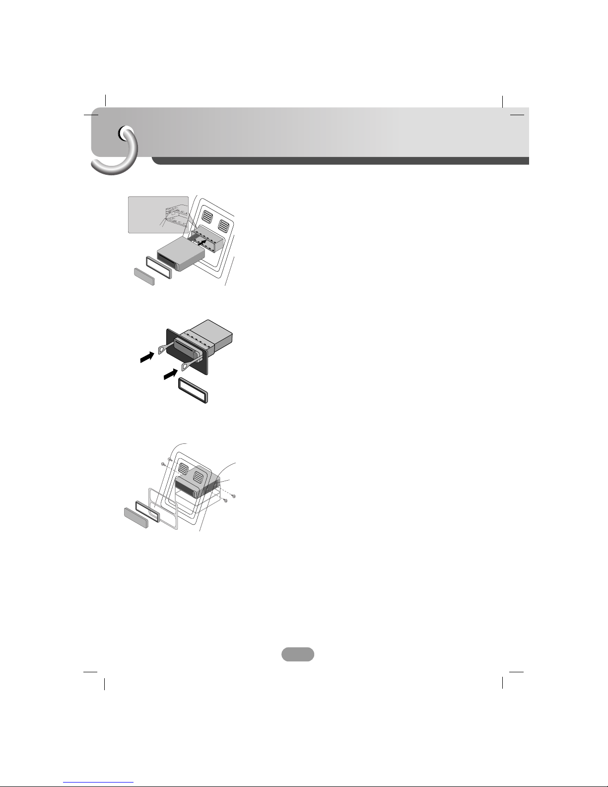
Basic Installation
Before installing, make sure that the ignition-switch is set to
OFF and remove the terminal of the car battery to avoid
short-circuiting.
1 Remove the existing receiver unit.
2 Make the necessary connections.
3 Install the installation sleeve.
4 Install the unit into the installation sleeve.
Removing the existing receiver unit.
If there is already an installation sleeve for the receiver unit in
the dashboard, it must be removed.
1 Remove the rear support from the unit.
2 Remove the control panel and trim ring from the unit.
3 Insert the lever Ainto the hole on one side of the unit.
Perform the same operation on the other side and pull the
unit out from the mounting sleeve.
ISO-DIN Installation
1 Slide the unit into the ISO-DIN frame.
2 Fit screws removed from the old unit.
3 Slide the unit and frame into the dash opening.
4 Install the dash panel or adapter plate.
5 Install the trim ring to the unit.
6 Install the control panel to the unit.
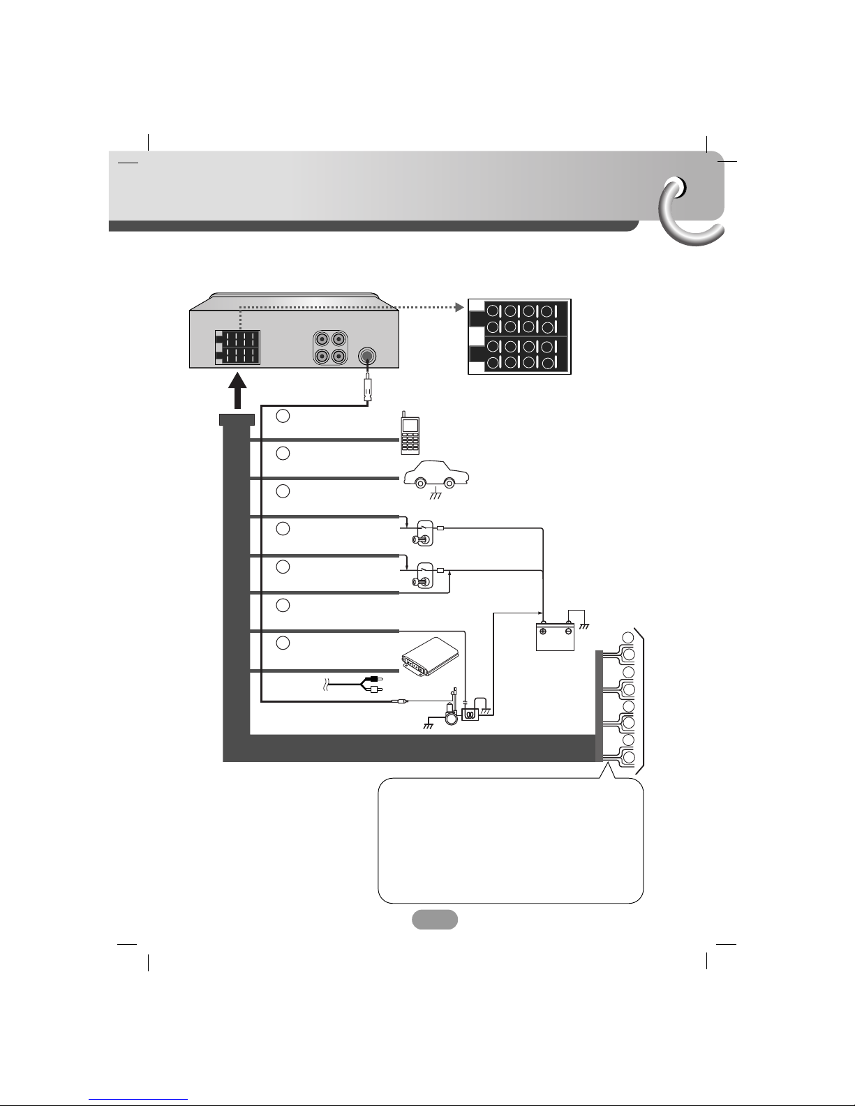
Connection diagram
9
Before connecting, make sure that the ignition switch is set to OFF, and remove the battery #
terminal to avoid short circuits.
BATTERY
POWER
Antenna
DIMMER SWITCH
IGNITION SWITCH
CONTROL RELAY
REMOTE ON (BLUE/WHITE)
AMPLIFIER
(Optional)
PHONE MUTE (ORANGE)
DIMMER (PINK)
TO IGNITION (RED)
GROUND(-) (BLACK)
POWER ANTENNA (BLUE)
TO BATTERY(+) (YELLOW)
1
2
3
4
5
6
7
8
1
2
3
4
5
6
7
8
B
A
A
A
A
A
A
A
A1
2
4
5
6
7
8
1
2
3
4
5
6
7
8
AA
BB
CC
B 11. Violet : Rear Right +
B 22. Violet/ Black Stripe : Rear Right –
B 33. Gray : Front Right +
B 44. Gray / Black Stripe : Front Right –
B 55. White : Front Left +
B 66. White/Black Stripe : Front Left –
B 77. Green : Rear Left +
B 88. Green/ Black Stripe : Rear Left –
To Speaker
To Vehicle
Connection
10
AAFrom antenna
BBTo the wiring of the vehicle colors of leads.
• BLACK : This lead is for the ground connection.
• ORANGE : This lead is for the phone line connection.
• PINK : This lead is for the dimmer line
connection.
• RED : This lead is for connection to the power
supply terminal when the ignition switch is
set to ACC.
• YELLOW : This lead is for connection to the battery
(back-up) terminal from which power is
always supplied.
• BLUE : This lead is for the power antenna
connection.
• BLUE/WHITE : This lead is for the remote amplifier on
connection.
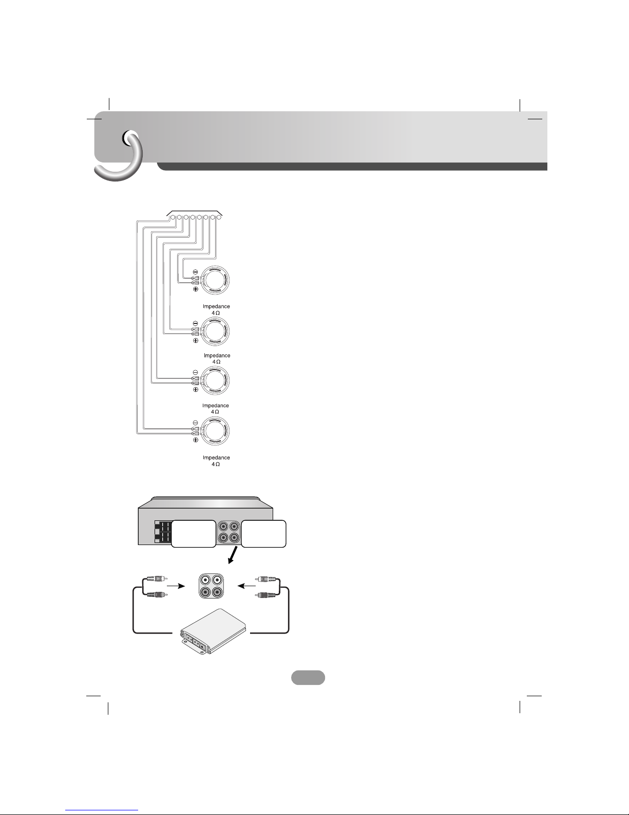
L
L
R
R
12 3 4 5 6 7 8
REAR
REAR
FRONT
FRONT
CCSpeaker Connections
Amplifier
To AUDIO IN
To AUDIO IN
To AUDIO OUT
FL (Front Left)
FR (Front Right)
RL (Rear Left)
RR (Rear Right)
Connecting to Auxiliary Equipment (Optional)
Connect the AUDIO OUTPUT jack of this unit to the AUDIO
INPUT jack of the Auxiliary Equipment.
Other manuals for LAC6700R
1
Table of contents
Other LG Car Receiver manuals


