Juwent UGW/D Series User manual

UGW/D
HEATING AND VENTILATION UNIT
Szymański, Nowakowski General Partnership
31 Lubelska Str., 08-500 Ryki
phone +48 81 883 56 00, fax +48 81 883 56 09
POLAND
I. CONTACTS
II. ORIGINAL INSTRUCTION MANUAL
III. WARRANTY TERMS AND CONDITIONS
IV. UNIT STARTUP REPORT
V. INSPECTION AND MAINTENANCE DOCUMENT
VI. SERVICE NOTIFICATION
VII. LIST OF SUBASSEMBLIES INSTALLED IN THE UNIT
Please read this instruction manual carefully before beginning any work.
RYKI 2013
ISSUE 1 EN
2www.juwent.com.pl
I. CONTACTS
Szymański, Nowakowski General Partnership
31 Lubelska Str., 08-500 Ryki
phone +48 81 883 56 00, fax +48 81 883 56 09
POLAND
Export department
mob.+48 502 087 841
mob.+48 664 465 243

3www.juwent.com.pl
II. ORIGINAL INSTRUCTION MANUAL
UGW/D HEATING AND VENTILATION UNITS
Size 10÷12

4www.juwent.com.pl
TABLE OF CONTENTS
1. INTENDED USE 5
2. DESIGNATIONS 5
3. OPIS URZĄDZENIA 5
4. TECHNICAL DATA 6
5. ADDITIONAL EQUIPMENT 7
6. TRANSPORT 8
7. SAFETY RECOMMENDATIONS 8
8. MOUNTING 9
9. WATER INSTALLATION 9
10. STEAM INSTALLATION 10
11. ELECTRICAL INSTALLATION 10
12. AUTOMATICS 12
13. DEVICE STARTUP 16
14. REPAIR, MAINTENANCE AND WITHDRAWAL FROM SERVICE 16
15. TROUBLESHOOTING 18
16. INFORMATION 18

5www.juwent.com.pl
1. INTENDED USE
UGW/D heating and ventilation units, size 10÷12, are intended to heat and ventilate such
compartment as:
»industrial halls
»warehouses
»workshops
»other objects of similar use
The units should be used only according to the intended use.
The manufacturer is not liable for using the units against the intended use and for any
damages arisen for this reason.
Heating and ventilation units cannot be used in the compartments with relative humidity
larger than 95% and air dust concentration over 5mg/m3.
The compartment can be served by one or larger number of the units, also by the units of different
sizes.
Units are suitable for mounting on walls at a height that allows direct air ow to the heated area.
Units are equipped with centrifugal fan allowing independent operation of the device or witch
attached additional equipment with air pressure drop up to 100 Pa.
The units can operate as heating units optionally with attached air lter at fan sucking side or as
heating and ventilation units with added intake boxes. The intake boxes enable to draw circulating
air, fresh air, or mixed in any proportion.
2. DESIGNATIONS
Heating and ventilation unit UGW/D- - - - - -
Size 10; 11; 12
Heating medium water (W); (oC);(MPa)
steam (P);(MPa)
Number of heating coil rows III, IV for water,
II, III for steam
Motor type
two speed three phase (TD);
single phase (J);
single speed three phase(T)
Speed 900/1400rpm, 1400rpm for size 10, 11
670 or 900 rpm for size 12
Type right (R) or left (L)
oC - heating medium temperature
MPa - permissible heating medium pressure
3. OPIS URZĄDZENIA
The unit consists of:
»highly efcient centrifugal fan in chemicals resistant version (1);
»water or steam heating coil (2);
All heating coils are made of bimetallic tubes i.e. steel core barrel and aluminium ribs rolled outside.
Standard water heating coils are made of tubes with the following dimensions: inner diameter
d=12,4mm, rib outer diameter D=38mm and ribs spacing 2,8mm and the steam heating coils are
made of tubes with d=21,4mm inner diameter, element outer diameter D=58mm and ribs spacing 5
mm. Connection spouts of the units with the steam and water heating coils are with threads.

6www.juwent.com.pl
For the bimetal water heaters the maximum temperature of heating medium is up to
150OC and the maximum operational pressure is up to 1,6Mpa.
For the steam heaters the maximum operational pressure is up to 0,6 Mpa.
There is a risk of heating medium freeze in the heater in the compartments with
the temperature below 0OC.
The risk can be reduced using an antifreeze thermostat (delivered at request), using antifreeze
heating media or removing water from the unit.
»casing (3) made of steel sheets with a single-row outlet grid allowing adjusting a direction of
supply air. The structure of grid blades protects against an automatic rearrangement of the blades.
The casing can be made of stainless steel sheets.
There are left or right types of units offered which means that with the right type the person looking
at the outlet grate sees the air intlet on the right.
4. TECHNICAL DATA
Basic dimensions
Unit size A
[mm]
B
[mm]
C
[mm]
D
[mm]
K
[mm]
L
[mm]
P
[mm]
Q
[mm]
a x b
[mm x mm]
h
[mm]
d Weight [kg]
water
steam
water III
water IV
steam II
steam III
UGW/D-10 519 945 373 345 291 260 563 90 295x400 385 ¾” ¾” 53 59 56 60
UGW/D-11 663 1245 479 410 342 342 794 116 390x520 490 1” 1” 87 96 78 95
UGW/D-12 808 1445 610 540 465 407 921 156 530x645 625 1¼” 1” 117 137 110 139
Unit environment and fan motor parameters
Unit size
Operation
temperature
[OC]
Max. air
humidity
[%]
Max. dust
content
[ mg/m3]
IP Insulating class
UGW/D-10,
11, 12 -15 ÷ +40OC95% 5 mg/m354 F
7www.juwent.com.pl
Units operational noise level
Unit size Speed
[rpm]
Noise level [dB(A)]
at the distance of 1m* at the distance of 5m*
UGW/D-10 900 59 55
1400 67 63
UGW/D-11 900 60 56
1400 70 66
UGW/D-12 670 62 58
900 68 64
*Level of operation noise - level of acoustic pressure with room absorbing capabilities A=100m2 and
directivity factor Q=2 taken into account.
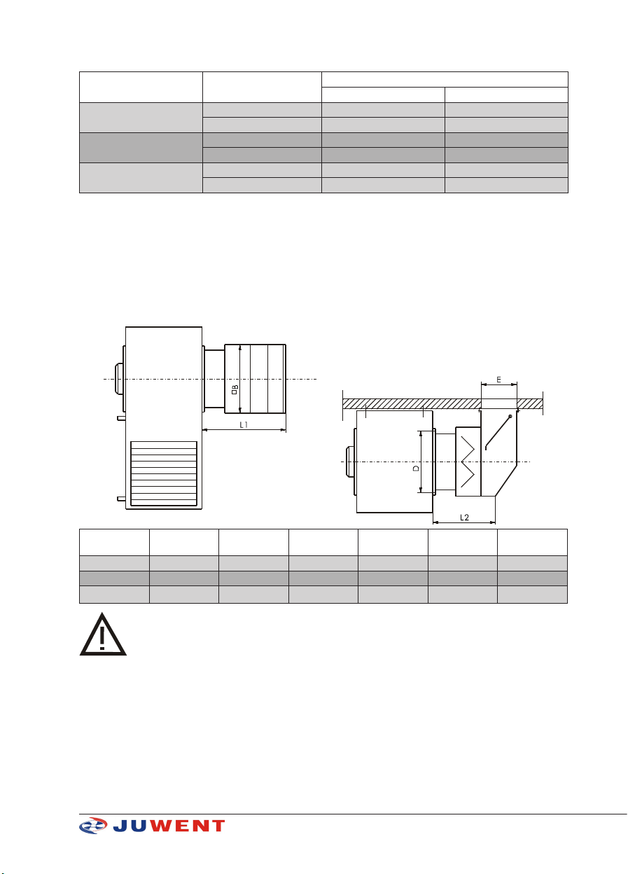
5. ADDITIONAL EQUIPMENT
Air intake boxes SkCz/D
They are use for drawing of fresh and recirculation air or of their mixture at any proportion.
Air intake boxes are made of powder-coated steel sheets.
Air throttles could be controlled manually or by use of servomotors.
Filter section is equipped in net or air lter of G-2 class.
Unit size Box size D
[mm]
B
[mm]
E
[mm]
L1
[mm]
L2
[mm]
UGW/D-10 SkCz/D-10 345 340 157 436 269
UGW/D-11 SkCz/D-11 410 443 200 497 285
UGW/D-12 SkCz/D-12 540 570 240 497 285
When equipping the unit with intake boxes with lter:
- air capacity is reduced by ~10%;
- thermal powers are reduced by ~5%.
The air deriving boxes are offered in left and right types. The left type is used in left type units and
right type is used in the right type units.

8www.juwent.com.pl
6. TRANSPORT
The delivered units are completely assembled, protected from outside by polyethylene foil against
pollution and weather impacts.
The Product Manual is delivered along with the unit.
The intake boxes constitute additional equipment and they are delivered separately at the customer’s
request.
The automatics elements delivered at the customer’s request are packed separately.
The units should be transported in one layer in a way preventing mechanical damages.
7. SAFETY RECOMMENDATIONS
Solutions minimizing a possibility of hazard to persons and property were applied when
designing and manufacturing the units. However, it does not eliminate all possible risks.
The heating and ventilation units should be used only in compliance with the instruction
manual.
The start-up, mounting, connection, inspections and repairs of the unit should be
executed by an authorized installer, the electric works should be executed by a person
having required certicates authorized to carry out electric works.
All service and repair works should be executed when voltage is off.
In case of the unit failure it is necessary to switch off the power supply to the electric
motor of the fan and close the heating medium supply to the heater immediately.
The unit can be used only when electric safety devices operate correctly.
It must be permanently connected to the electric installation equipped with protective
(earth) terminal, residual current device and service switch.
It is necessary to pay attention not to change the protection lead to the power lead.
The operation of the unit with the fan without a protective net is forbidden.
The heaters of the units can be supplied with water or steam of very high temperature
(up to 160OC) what forces the users to be particularly carful.
A correct selection of ttings (including drain valves) by the designer of the installation
is a condition of safe operation of the steam heater.
Only original spare parts should be used.
Note for the user! The mounting or use of the heating and ventilation unit against the
instruction manual makes the threat of unit damage, creates the hazard to persons and
property and causes the loss of warranty.

9www.juwent.com.pl
Due to the structure the unit does not emit harmful radiation.
Although the unit was designed and manufactured in compliance with the requirements of the
standards, according to their state at the moment of production launch, a probability of injury or
health loss when using the unit is not to be avoided. This probability is connected with a frequency of
access to the unit in the course of its use, cleaning or repair, presence of persons within a dangerous
zone, acting against the safety rules specied in the instruction manual.
The gravity of body injury or deterioration of health condition depends on many factors that often
can be foreseen only partially, taking them into consideration in the structure of the unit, specifying
them and warning against them in the instruction manual.
Therefore there is a residual risk when the operator does not observe the recommendations and
guidelines included in the instruction manual.
8. MOUNTING
Hanging of the unit
For hanging the unit on the construction columns the catches are used (3 pcs) located at the rear
of the casing.
Unit size E
[mm]
F
[mm]
H
[mm]
UGW/D-10 240 28 760
UGW/D-11 345 28 1030
UGW/D-12 545 28 1180
Minimal distance of the heating unit from construction partitions at the unit sides is ~ 30 cm.
Hanging the units with intake boxes
Intake boxes should be screwed to the unit, the unit hanged on the wall and the intake box ange
screwed to the wall.
9. WATER INSTALLATION
Unit supply could be from top or lower spout. In new installations, better results are obtained with
lower spout supply due to the heater venting easier.
It is recommended:
»to use cut-off valves upstream and downstream the unit to enable its dismounting without
the necessity to drain the supply installation
»installation of the valve (recommended by Juwent) on medium supply spout.
The venting and draining of the heaters of the units is foreseen centrally in the network.
The vents and drain valves located in the installation outside the unit should be used.
The imprecise venting of the heater can be a reason for which the unit does not reach
planned parameters.
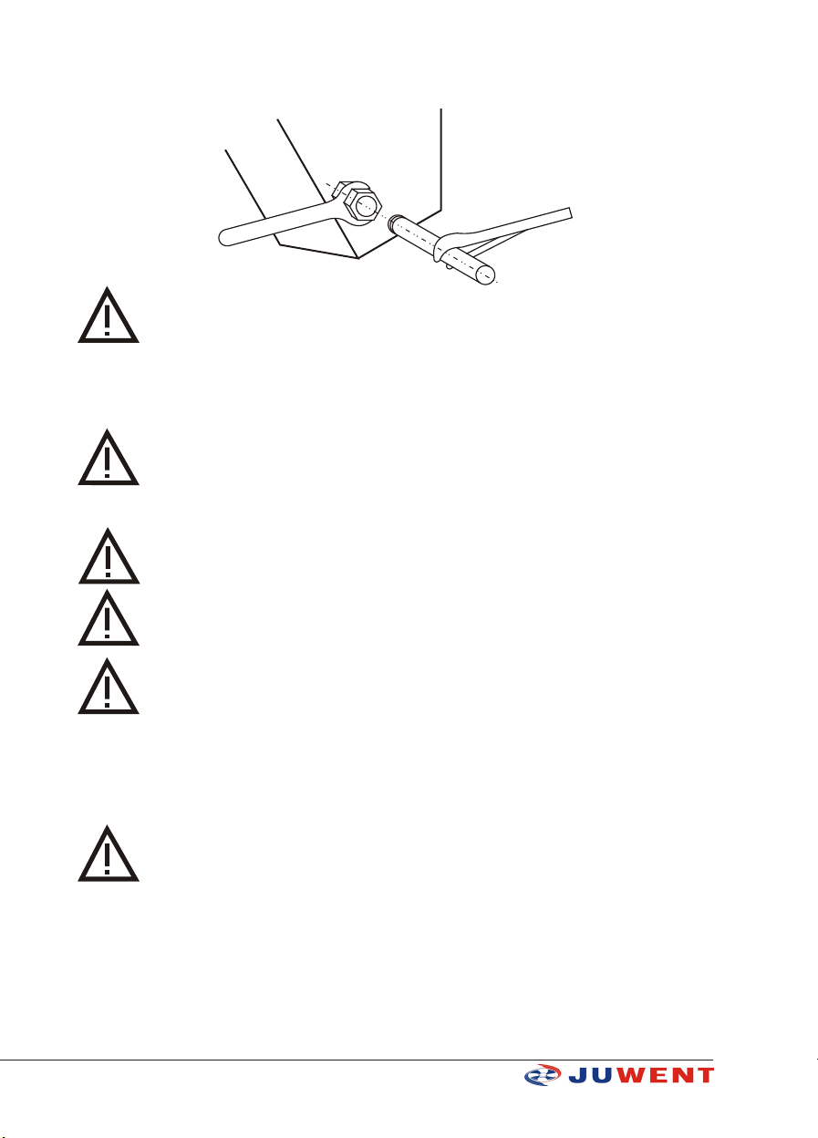
The weight of installation pipes should not rest on the spouts of the heater.
10 www.juwent.com.pl
When connecting the heater to the heating network the spouts of the heater should be protected
against breaking in a way presented in the picture.
The heater damages arisen for the afore-mentioned reason are not covered by the
warranty.
10. STEAM INSTALLATION
The steam heaters should be supplied from the top.
A correct selection of ttings (including drain valves) by the designer of the installation
is a condition of safe operation of the steam heater.
11. ELECTRICAL INSTALLATION
The electric installation and the connection of power to the unit must be executed
according to the relevant requirements of the standards and construction regulations.
The electric connections, start-up, inspections and electric repairs may be executed only
by an electrician who has required certicates to carry electric works and got acquainted
with the instruction manual.
Before the connection it is necessary to make sure whether the voltage value and power
system frequency are compliant with the data specied on the rating plates of the units.
In case of noncompliance the unit should not be connected.
The units are equipped with single (1~230 V/50 Hz) or three-phase (3~400 V/50 Hz). The units should
be powered from the main switchboard equipped with a main switch, differential protection device,
protective (earth) terminal and overload and short-circuit protection devices (motor switches). The
setup of overload protection cannot be higher than rated current of the motor (specied on the
rating plate of the motor of the unit).
The lack of required motor safety devices and non-connection of thermal contact TK to
the control circuit cause the loss of warranty.
The lead powering the motor of the fan should be inserted to the terminal box and fastened to the
protective supports by means of clamp bands.
Electrical connection of the motor must comply with the wiring diagrams placed in the terminal box.
Examples of wiring diagrams and control devices are given in Figures 1, 2 and 3.
This manual suits for next models
3
Table of contents
Other Juwent Fan manuals


Popular Fan manuals by other brands

ELTA FANS
ELTA FANS H03VV-F installation guide

Hunter
Hunter 20714 Owner's guide and installation manual

Emerson
Emerson CARRERA VERANDA CF542ORB00 owner's manual

Hunter
Hunter Caraway Owner's guide and installation manual

Panasonic
Panasonic FV-15NLFS1 Service manual

Kompernass
Kompernass KH 1150 operating instructions


