ICP DAS USA I-7531-FD User manual

I-7531-FD CAN Repeater User Manual (ver. 1.0, 2021/10/21) ------1
User Manual
Warranty
All products manufactured by ICP DAS are under
warranty regarding defective materials for a period of one
year from the date of delivery to the original purchaser.
Warning
ICP DAS assumes no liability for damages resulting
from the use of this product. ICP DAS reserves the right to
change this manual at any time without notice. The
information furnished by ICPDAS is believed to be accurate
and reliable. However, no responsibility is assumed by ICP
DAS for its use, or for any infringements of patents or other
rights of third parties resulting from its use.
Copyright
Copyright 2021 by ICP DAS. All rights are reserved.
Trademark
The names used for identification only may be
registered trademarks of their respective companies.
The I-7531-FD CAN Repeater

I-7531-FD CAN Repeater User Manual (ver. 1.0, 2021/10/21) ------2
Tables of Content
Tables of Content...........................................................................................2
1Introduction.............................................................................................3
1.1 Features..........................................................................................4
1.2 Specifications ................................................................................4
2Technical data.........................................................................................5
2.1 Block Diagram................................................................................5
2.2 Appearance ....................................................................................6
2.3 Pin Assignment..............................................................................7
2.4 Wire Connection ............................................................................9
2.5 Status LED......................................................................................9
2.6 Terminator Resistor Setting........................................................10
2.7Baud rate and wire length of CAN bus.......................................12
3Dimension .............................................................................................14
I-7531-FD CAN Repeater User Manual (ver. 1.0, 2021/10/21) ------3
1 Introduction
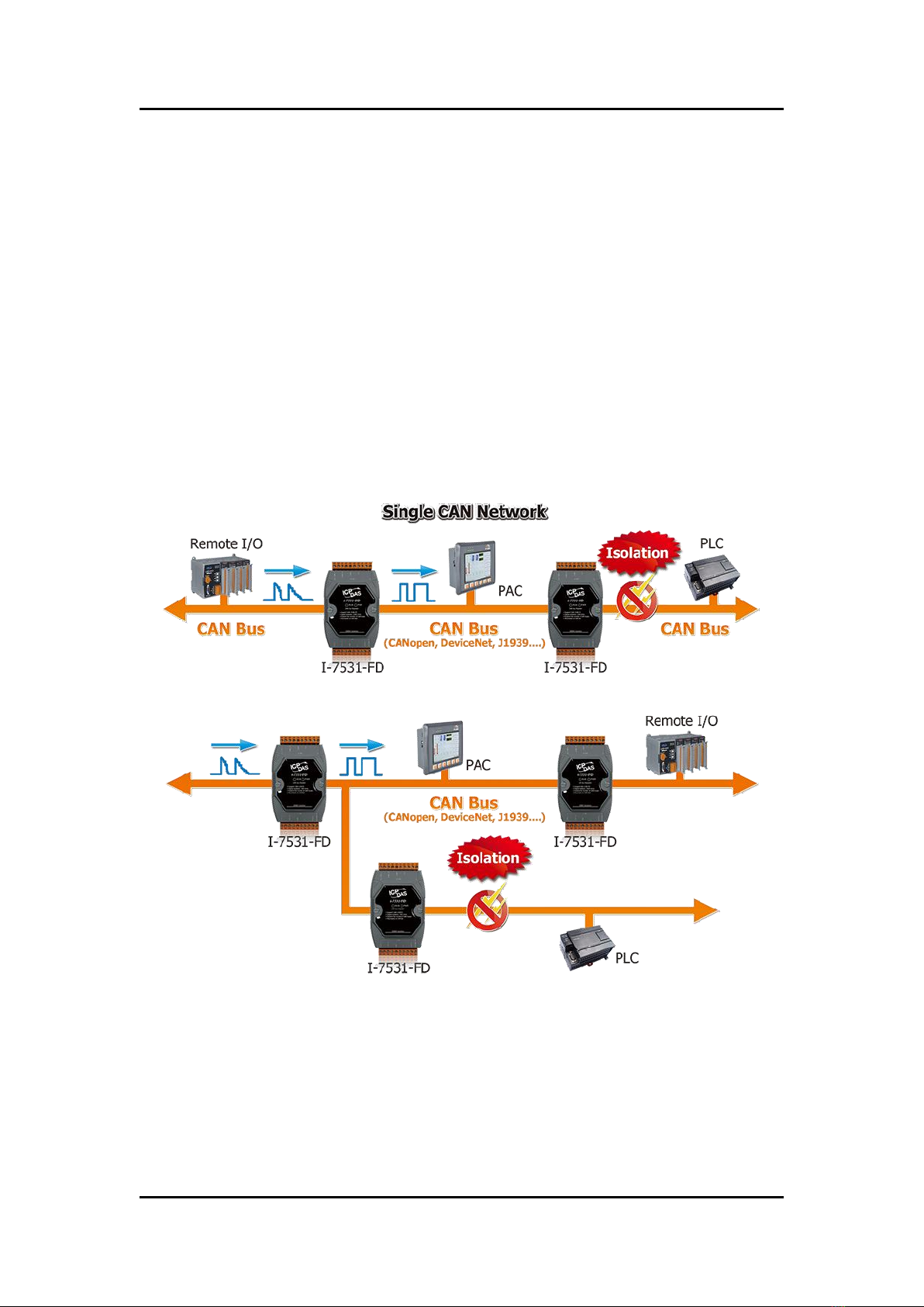
The I-7531-FD is a CAN/CAN FD signal repeater, which can connect two
or more CAN networks with the same baud rate. Based on the signal repeat
function of I-7531-FD, users can use differentnumbers of I-7531-FD to combine
tree-shaped and star-shaped CAN network topology, and when there are too
many devices on the CAN network, using I-7531-FD can increase the driving
force of the CAN signal to drive more CAN devices. In addition, the CAN side
of the I-7531-FD has a digital isolation of 2500 Vrms, and the CAN side and the
power side also provide 3000 V DC-DC isolation protection, which can
effectively isolate the noise interference between CAN networks ,and achieve
protection the purpose of a specific CAN network.
Figure1. Application

I-7531-FD CAN Repeater User Manual (ver. 1.0, 2021/10/21) ------4
1.1 Features
Supported CAN specification 2.0A/B and CAN FD
Fully compatible with the ISO 11898-2 standard
Detected CAN bus baud rate automatically, maximum support 8000
kbps
1.2 Specifications
CAN
Ports
2
Baud Rate
CAN bus: 5 k ~ 800 kbps
CAN FD: Arbitration rate up to 1000 kbps,
data rate up to 8000 kbps
(Note) The data rates are verified by tests, but
user-defined baud rates are possible, so the
maximum data rate will depend on the
concrete operating conditions (cable length,
remote stations, etc.).
Isolation
2500 Vrms for digital isolation, and 3000 V for DC-DC
Terminal Resistor
Build in 120 Ω terminal resistor and support jumper to
select
Specification
ISO-11898-2, CAN 2.0A/B and CAN FD
(CAN FD support ISO and Non-ISO standards)
Time Delay
Typ. 175ns (corresponds to ~35m CAN bus length)
Power
Input Range
+10 VDC ~ +30 VDC
Consumption
1 W
Mechanical
Casing
Plastic
I-7531-FD CAN Repeater User Manual (ver. 1.0, 2021/10/21) ------5
Mechanical
Dimensions (mm)
72 x 118 x 33 (W x L x H)
Installation
DIN-Rail
Environmental
Operating Temperature
-25 ~ +75 °C
Storage Temperature
-30 ~ +80 °C
Humidity
10 ~ 90% RH, Non-condensing
2 Technical data
2.1 Block Diagram
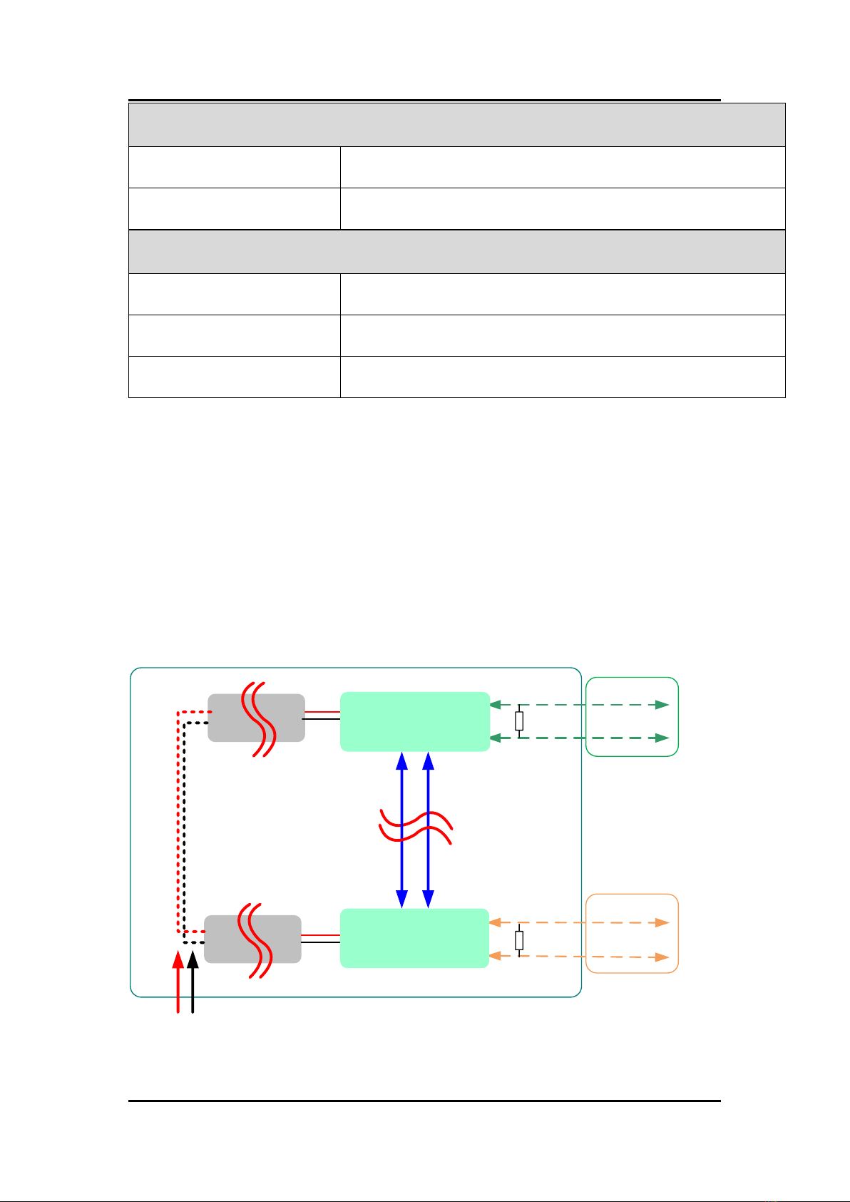
Figure 2 is a block diagram illustrating the functions of the I-7531-FD
module. Power supply are with 3000 VDC galvanic isolated between each CAN
port. Futhermore, there is digital-isolation 2500 Vrms between two CAN ports.
2500 Vrms
Digital Isolation
DC
DC
3000 VDC
Isolation
DC
DC
3000 VDC
Isolation
+10 VDC ~ +30 VDC
Block Diagram of I-7531-FD
CAN_L
120 Ohm
CAN_H
CAN_H
CAN_L
120 Ohm
Physical CAN layer
Physical CAN layer
CAN Port 1
CAN Port 2
Figure2. Block Diagram

I-7531-FD CAN Repeater User Manual (ver. 1.0, 2021/10/21) ------6
2.2 Appearance
i-7531
CAN bus Repeater
‧Support CAN / CAN FD
‧Digital-isolation: 2500 Vrms
‧Expand the number of CAN buses
‧Moun table on DIN Rail
3000V Isolation
GND
11
(CAN)
20 CAN_L
CAN_H
FG
GND
10
(CAN)
1
CAN_L
CAN_H
FG
(R)VS+
(B)GND
CAN Port 2
Status LED of
Power &
Communication
CAN Port 1 Power Input
Frame Ground
Frame Ground
RUN PWR
Figure3. Apperance
I-7531-FD CAN Repeater User Manual (ver. 1.0, 2021/10/21) ------7
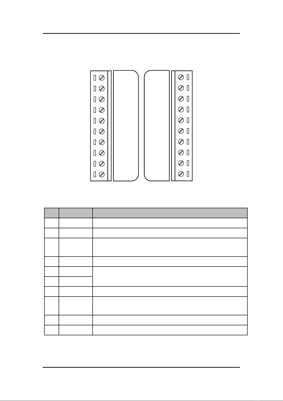
2.3 Pin Assignment
Figure4. Pin Aassignment
Table1. Pin Description
Pin
Name
Description
1
CAN_L
CAN_Low. Signal Line of CAN port 1.
3
CAN_H
CAN_High. Signal Line of CAN port 1.
5
GND
CAN_Ground (or CAN_GND), voltage level of ground of CAN_L
and CAN_H in CAN port 1.
7
FG
Frame Groud.
9
(R)VS+
Power input +10VDC ~ +30VDC.
10
(B)GND
14
FG
Frame Groud.
16
GND
CAN_Ground (or CAN_GND), Voltage level of ground of CAN_L
and CAN_H in CAN port 2.
18
CAN_H
CAN_High. Signal Line of CAN port 2.
20
CAN_L
CAN_Low. Signal Line of CAN port 2.
GND
11
(CAN)
20 CAN_L
CAN_H
FG
GND
10
(CAN)
1
CAN_L
CAN_H
FG
(R)VS+
(B)GND

I-7531-FD CAN Repeater User Manual (ver. 1.0, 2021/10/21) ------8
Note 1:
In normal situation, the CAN_GND does not need to be wired, but
the CAN_GND’s voltage level of different CAN devices are not
equal in some case. When in this situation, it maybe cause some
problems and reduce the stability of the CAN bus system. The
user can connect CAN_GND of these CAN devices to let the
voltage level be same and eliminate this situation.
Note 2:
Electronic circuits are susceptible to electrostatic discharge
(ESD) and will get worse when encountering continental
climates, so F.G. provides a path for ESD to lead to the earth
ground, thereby enhancing the module's ability to protect against
static electricity. If the user wants to use F.G., both pin 7 and pin
14 need to be connected to the earth ground, because the two
pins are not connected inside the module.
I-7531-FD CAN Repeater User Manual (ver. 1.0, 2021/10/21) ------9
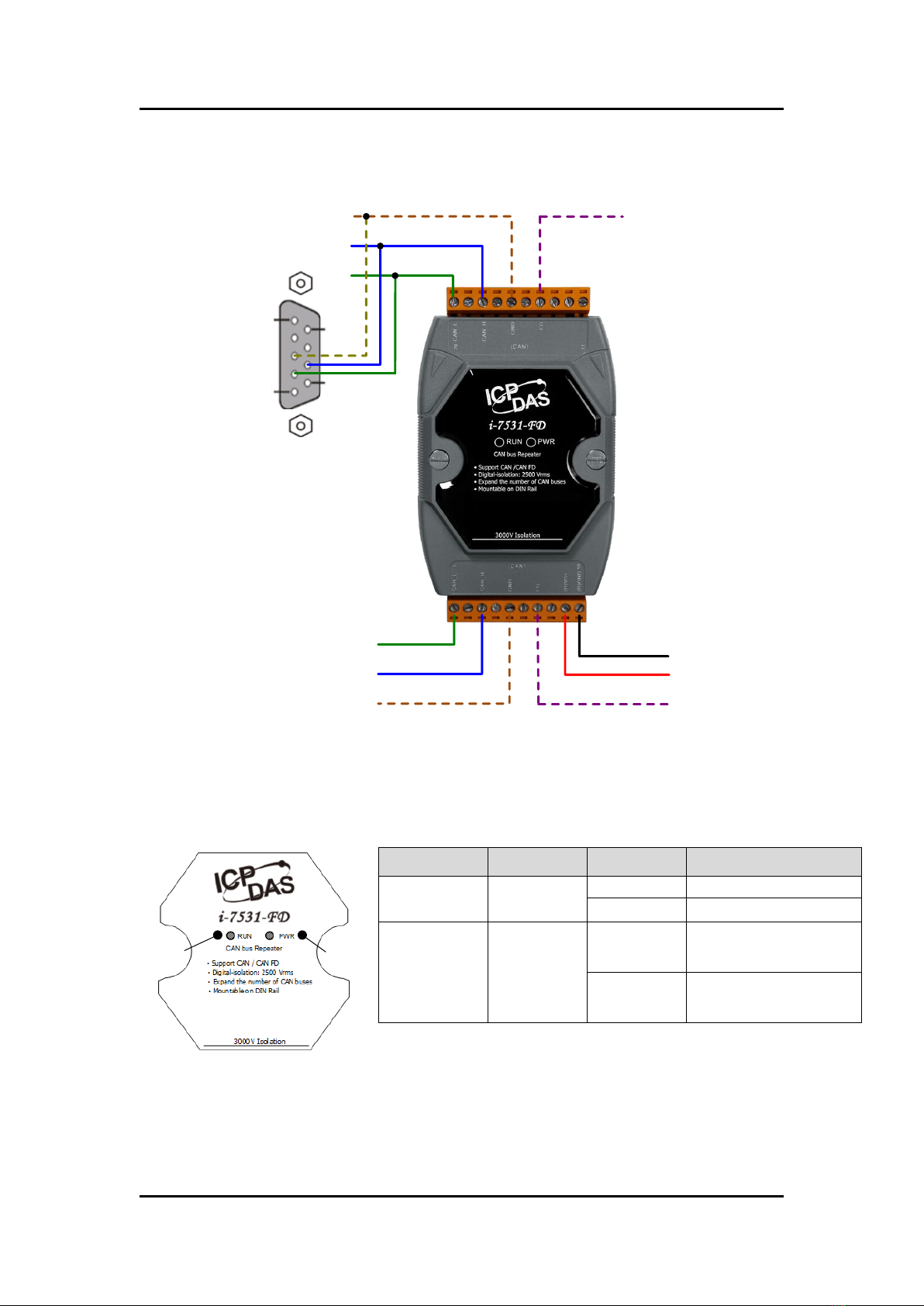
2.4 Wire Connection
CAN DEVICE CAN_H
CAN_L
Power GND
+10VDC ~ +30VDC
CAN_H
CAN_L
CAN_GND
CAN_GND
1
5
6
9
Frame Ground
9-Pin D-sub
Male connector
Frame Ground
Figure5. Wire Connection
2.5 Status LED
LED
Color
Status
Description
1
(PWR)
Red
ON
Power on
OFF
Power off
2
(RUN)
Green
Blink
In communication
OFF
No data in
communication
Note:
RUN LED's twinkling rate correlates with baud rate of CAN bus.
User may see no twinkling when the twinkling period is too short
because of the higher baud rate of CAN bus. Besides, the LED
could look like always on when bus loading is heavy.
1
2
I-7531-FD CAN Repeater User Manual (ver. 1.0, 2021/10/21) ------10
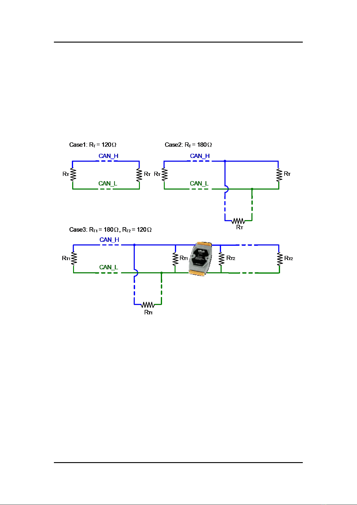
2.6 Terminator Resistor Setting
According to the ISO 11898-2 specifications, the bus line of CAN_H and
CAN_L must be terminated by resistor for proper operation. The equivalent
resistance between CAN_H and CAN_L should be 60Ω. There are some
examples below.
Figure6. Terminator Resistor
Other manuals for I-7531-FD
2
Table of contents
Other ICP DAS USA Repeater manuals

ICP DAS USA
ICP DAS USA CAN Repeater I-7531 User manual

ICP DAS USA
ICP DAS USA CAN Repeater I-7531 User manual

ICP DAS USA
ICP DAS USA ZT-2510 Series User manual

ICP DAS USA
ICP DAS USA CAN Repeater I-7531 User manual

ICP DAS USA
ICP DAS USA I-7531-FD User manual

ICP DAS USA
ICP DAS USA I-7531-FD User manual

ICP DAS USA
ICP DAS USA ZB-2510 User manual

ICP DAS USA
ICP DAS USA CAN Repeater I-7531 User manual


