Cisco NXK-ACC-KIT2-2RU User manual

Installing the Chassis
•Installation Options with Rack-Mount Kits, on page 1
•Install a Rack, on page 1
•Unpacking and Inspecting a New Switch, on page 2
•Planning How to Position the Chassis in the Rack, on page 3
•Installing the Chassis in a Four-Post Rack, on page 3
•Grounding the Chassis, on page 10
•Starting the Switch, on page 12
Installation Options with Rack-Mount Kits
The rack-mount kit enables you to install the switch into racks of varying depths. You can position the switch
with easy access to either the port connections or the fan and power supply modules.
You can install the switch using the following rack-mount options:
• Rack-mount kit (NXK-ACC-KIT2-2RU) which you can order from Cisco.
For four post racks.
• Rack-mount kit (N9K-C9300-RMK) which you can order from Cisco.
For four post racks.
The rack or cabinet that you use must meet the requirements listed the in General Requirements for Cabinets
and Racks section.
You are responsible for verifying that your rack and rack-mount hardware comply with the guidelines that
are described in this doc.
Note
Install a Rack
Before you install the switch, you must install a standard four-post, 19-inch EIA data center rack (or a cabinet
that contains such a rack) that meets the requirements listed in Overview of Racks.
Installing the Chassis
1

Step 1 Bolt the rack to the concrete subfloor before moving the chassis onto it.
Statement 1048—Rack Stabilization
The rack stabilizing mechanism must be in place, or the rack must be bolted to the floor before installation or
servicing. Failure to stabilize the rack can cause bodily injury.
Warning
Step 2 If the rack has bonded construction, connect it to the earth ground. This action enables you to easily ground the switch
and its components and to ground your electrostatic discharge (ESD) wrist strap to prevent damaging discharges when
you handle ungrounded components before installing them.
Step 3 Include one or two power sources at the rack. For AC power, provide a power receptacle. For DC power, provide a circuit
breaker with terminals for connecting power cables.
Statement 1018—Supply Circuit
To reduce risk of electric shock and fire, take care when connecting units to the supply circuit so that wiring
is not overloaded.
Warning
If you are not using power redundancy or are using n+1 redundancy, you need only one power source. If you
are using n+nredundancy, you need two power sources.
Note
Unpacking and Inspecting a New Switch
Before you install a new chassis, you need to unpack and inspect it to be sure that you have all the items that
you ordered and verify that the switch was not damaged during shipment. If anything is damaged or missing,
contact your customer representative immediately.
When you handle the chassis or its components, you must follow ESD protocol at all times to prevent ESD
damage. This protocol includes but is not limited to wearing an ESD wrist strap that you connect to the earth
ground.
Caution
Do not discard the shipping container when you unpack the switch. Flatten the shipping cartons and store
them. If you need to move or ship the system in the future, you will need this container.
Tip
Step 1 Compare the shipment to the equipment list that is provided by your customer service representative and verify that you
have received all of the ordered items.
The shipment should include the following:
• Switch chassis, which includes the following installed components:
• Two power supplies (any combination of the following with the airflow direction being the same as for the fan
modules):
Installing the Chassis
2
Installing the Chassis
Unpacking and Inspecting a New Switch

• fan modules (all fan and power supply modules must have the same airflow direction)
• Switch accessory kit
Step 2 Check the contents of the box for damage.
Step 3 If you notice any discrepancies or damage, send the following information to your customer service representative by
email:
• Invoice number of the shipper (see the packing slip)
• Model and serial number of the missing or damaged unit
• Description of the problem and how it affects the installation
Planning How to Position the Chassis in the Rack
The switch is designed so that you can have coolant air flow through the switch in one of the two following
directions:
• Enter the port side and exhaust out the power supply side (port-side intake airflow)
• Enter the power supply side and exhaust out the port side (port-side exhaust airflow)
For port-side intake airflow, the switch must have port-side intake fan and AC power supply modules with
one or more of the following colorings:
• Burgundy coloring on fan modules and AC power supplies
For port-side exhaust airflow, the switch must have port-side exhaust fan and AC power supply modules with
one or more of the following colorings:
• Blue coloring on fan modules and AC power supplies
You can plan the positioning of the switch so that its ports are located close to ports on connected devices or
so that the fan and power supply modules are conveniently located in a maintenance aisle, and then order the
modules that move coolant air in the appropriate direction from the cold aisle to the hot aisle.
All fan and power supply modules in the same switch must operate with the same direction of airflow and
the air intake portion of the switch must be located in a cold aisle.
Note
Installing the Chassis in a Four-Post Rack
Before you install the chassis, be sure that the rack is fully secured to the data center floor.
Installing the Chassis
3
Installing the Chassis
Planning How to Position the Chassis in the Rack
Installing the Switch using the NXK-ACC-KIT2-2RU Rack-Mount Kit
To install the switch, you must attach inner rails to the chassis, attach the outer rails to the rack, slide the
switch onto the outer rails, and secure the switch to the rack with the retainer screws. Typically, the front of
the rack is the side easiest to access for maintenance.
Before you begin
• You have inspected the switch shipment to ensure that you have everything ordered.
• Make sure that the switch rack-mount kit includes the following parts:
• Rack-mount inner rails (2)
• Rack-mount outer rails (2)
• Flat head screws (12)
• The rack is installed and secured to its location.
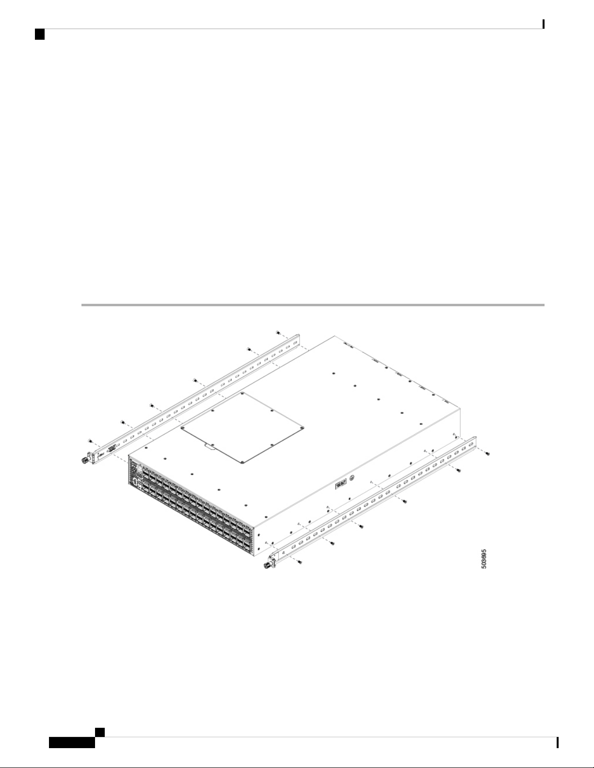
Step 1 Install the two inner rails to the sides of the chassis using flat-head screws, as shown in the following illustration:
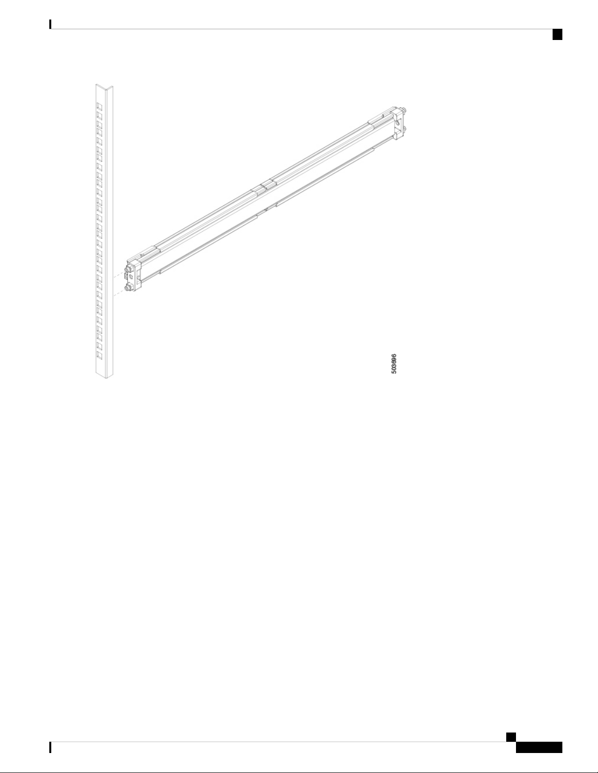
Step 2 Install the two outer rails to the front posts of the rack by aligning the rails to the post holes, as shown in the following
illustration:
Installing the Chassis
4
Installing the Chassis
Installing the Switch using the NXK-ACC-KIT2-2RU Rack-Mount Kit
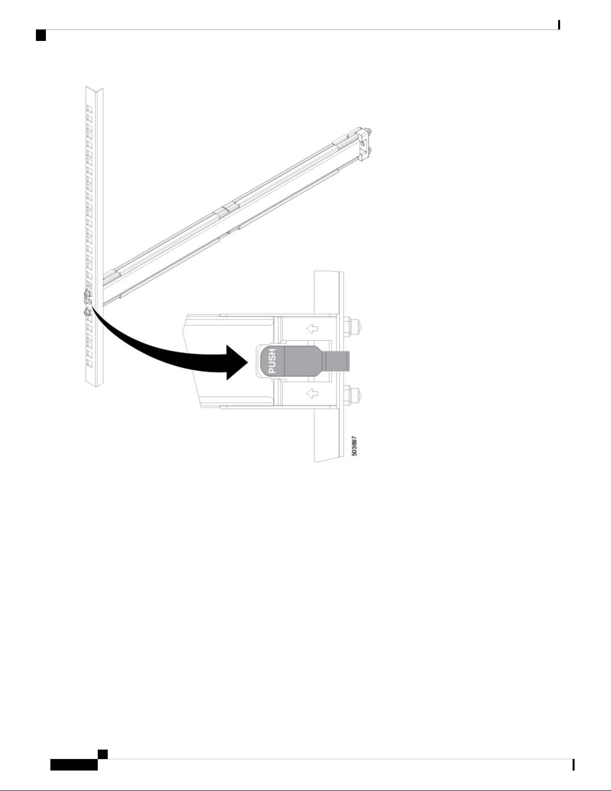
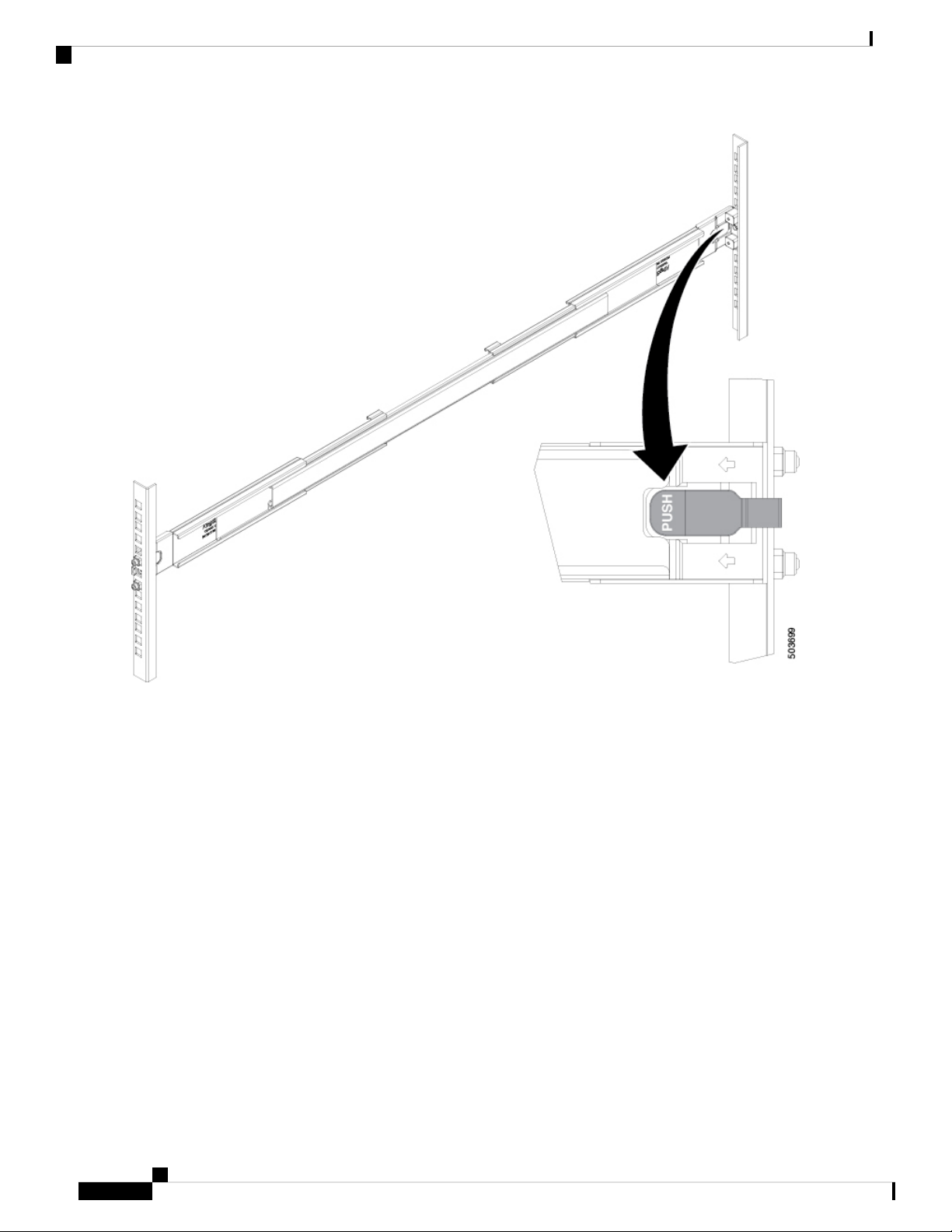
Step 3 Fasten the two outer rails to the front posts of the rack by pushing the latch into place, as shown in the following illustration:
Installing the Chassis
5
Installing the Chassis
Installing the Switch using the NXK-ACC-KIT2-2RU Rack-Mount Kit
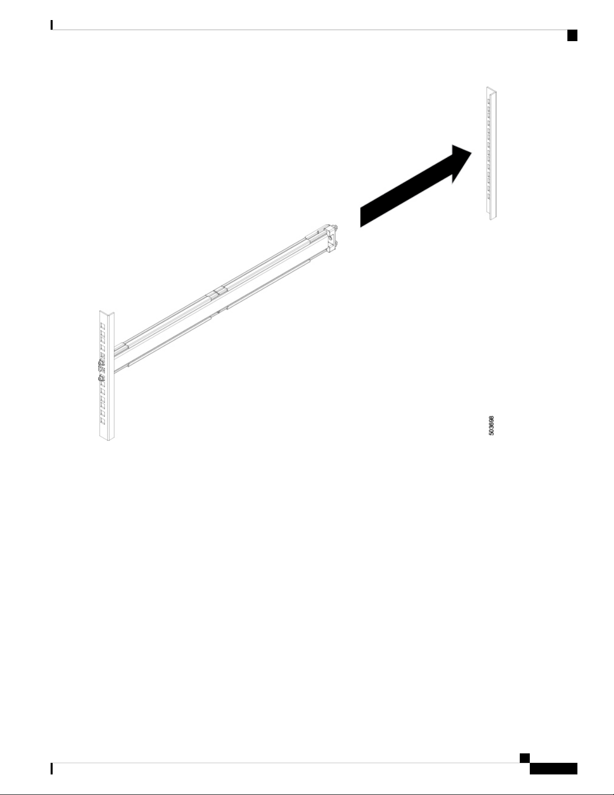
Step 4 Install the two outer rails to the back posts of the rack by extending them into place, as shown in the following illustration:
Installing the Chassis
6
Installing the Chassis
Installing the Switch using the NXK-ACC-KIT2-2RU Rack-Mount Kit
Step 5 Fasten the two outer rails to the back posts of the rack by pushing the latch into place, as shown in the following illustration:
Installing the Chassis
7
Installing the Chassis
Installing the Switch using the NXK-ACC-KIT2-2RU Rack-Mount Kit
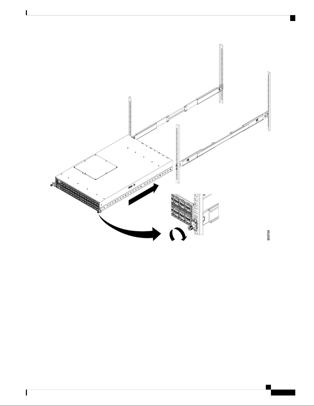
Step 6 If installing from the front of the rack, slide the chassis into the rack by aligning the inner rails into the outer rails, and
sliding the chassis back until the front panel is flush with the front of the rack. Then secure the retainer screws on the
inner rails into the rack, as shown in the following illustration:
Installing the Chassis
8
Installing the Chassis
Installing the Switch using the NXK-ACC-KIT2-2RU Rack-Mount Kit
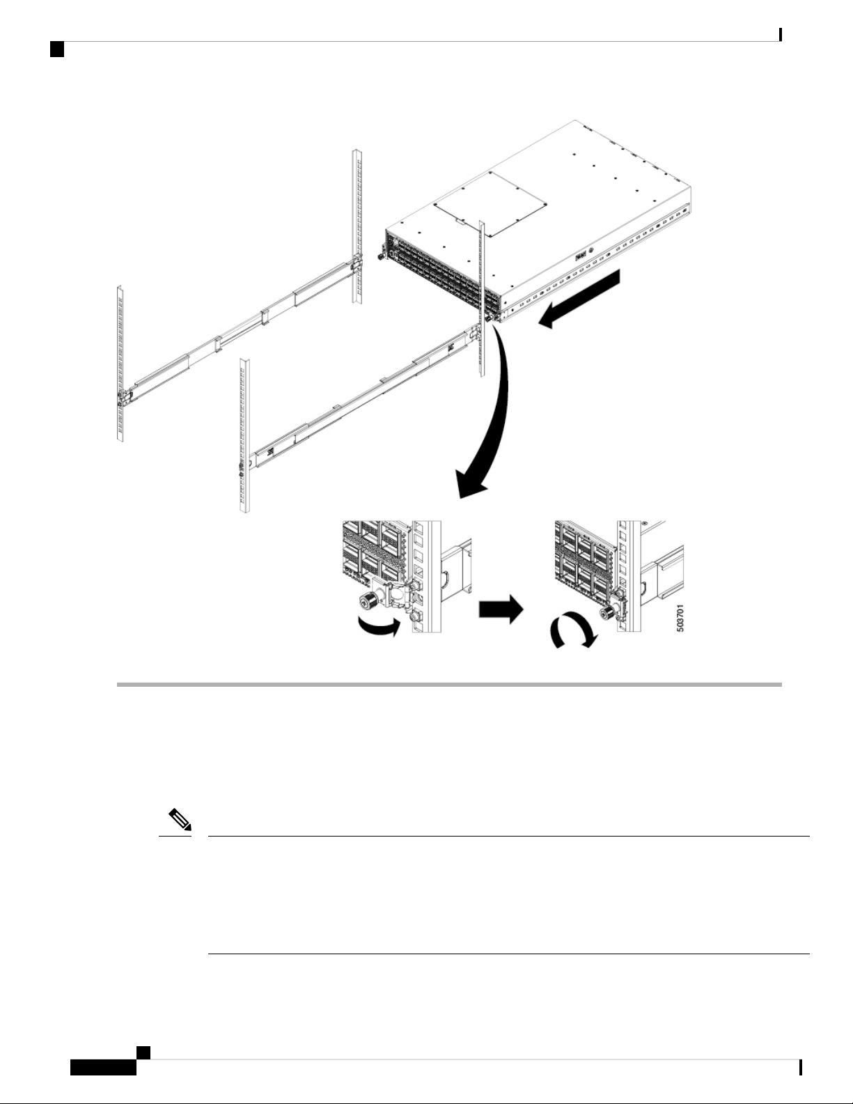
Step 7 If installing from the back of the rack, slide the chassis into the rack by aligning the inner rails into the outer rails, and
sliding the chassis forward until the front panel is flush with the front of the rack. Then slide the retainer screws out to
align with the rack and then secure the thumb-screws on the inner rails into the rack, as shown in the following illustration:
Installing the Chassis
9
Installing the Chassis
Installing the Switch using the NXK-ACC-KIT2-2RU Rack-Mount Kit
Grounding the Chassis
The switch chassis is automatically grounded when you properly install the switch in a grounded rack with
metal-to-metal connections between the switch and rack.
An electrical conducting path shall exist between the product chassis and the metal surface of the enclosure
or rack in which it is mounted or to a grounding conductor. Electrical continuity shall be provided by using
thread-forming type mounting screws that remove any paint or non-conductive coatings and establish a
metal-to-metal contact. Any paint or other non-conductive coatings shall be removed on the surfaces between
the mounting hardware and the enclosure or rack. The surfaces shall be cleaned and an antioxidant applied
before installation.
Note
Installing the Chassis
10
Installing the Chassis
Grounding the Chassis
This manual suits for next models
1
Table of contents
Other Cisco Rack & Stand manuals


Popular Rack & Stand manuals by other brands

Salamander
Salamander Acadia AC/W/L400/WH Assembly instructions

Fohhn
Fohhn VAT-09 Mounting instruction

ricoo
ricoo FS0522 quick start guide

AMSOIL
AMSOIL BMK-22 Installation and service instructions

Kargo Master
Kargo Master 48220 installation guide

Milestone AV Technologies
Milestone AV Technologies SIMPLICITY SLF2 installation instructions


