Applied Satellite Engineering ComCenter-II 'Outdoor' User manual

Unpacking Preparation Installation Warranty
Operation
AppendixOverview
REV-3.0 [3-17-11] 1
ComCenter-II ‘Outdoor’ Product Manual
Table of Contents
Overview .................................................................................................................................................................................................2
Contacts ...................................................................................................................................................................................................2
Preface .....................................................................................................................................................................................................2
Product Features .....................................................................................................................................................................................2
Safety Information ....................................................................................................................................................................................3
Un-Packing ..............................................................................................................................................................................................6
In Case of Damages or Missing Parts ......................................................................................................................................................6
What’s Inside the Box ...............................................................................................................................................................................6
Tools Required for Installation .................................................................................................................................................................6
Preparation ..............................................................................................................................................................................................7
Pre-Use Testing of Components & Connectivity .......................................................................................................................................7
Accessing Internal SIM Slot ...................................................................................................................................................................7
Installing SIM Card .................................................................................................................................................................................7
Re-Assembling ComCenter Casing .......................................................................................................................................................7
Locating Satellite-Viewable Work Area ...............................................................................................................................................8
Attaching Phone and Power ..................................................................................................................................................................8
Activating and Testing System ................................................................................................................................................................8
Installation ...............................................................................................................................................................................................9
Attaching Bracket to Pole ........................................................................................................................................................................9
Routing Cables .........................................................................................................................................................................................9
Connecting the ComCenter ...................................................................................................................................................................9
Attaching Cable to ComCenter ...............................................................................................................................................................10
Attaching ComCenter to Bracket ..........................................................................................................................................................10
Attaching Power and Phones to Wall Plate .............................................................................................................................................10
Operation ...............................................................................................................................................................................................11
Typical Start-Up Sequence (Overview) ..................................................................................................................................................11
Power-On Conrmation .........................................................................................................................................................................11
Ready-For-Use Conrmation ................................................................................................................................................................11
Connecting To Your Computer Or Network Via Ethernet .........................................................................................................................12
Changing Modes ...................................................................................................................................................................................12
Finding your ComCenter With ASE Device Manager .........................................................................................................................13
Changing the Ethernet Connection Mode Using POTS/RJ-11 .............................................................................................................14
Changing the Ethernet Connection Mode Using Embedded Webpage ...............................................................................................14
Accessing System Settings ...................................................................................................................................................................15
Accessing ComCenter II Settings .........................................................................................................................................................16
Accessing ComCenter II Settings and Features ....................................................................................................................................17
General Use - Voice Calls ...................................................................................................................................................................18
General Use - Text Messaging ............................................................................................................................................................19
General Use - Data Calls ....................................................................................................................................................................19
Special Features ..................................................................................................................................................................................20
Specications .......................................................................................................................................................................................23
Appendix ...............................................................................................................................................................................................24
Status and Error Tones ..........................................................................................................................................................................24
Warranty ...............................................................................................................................................................................................25
Declaration of Conformity ......................................................................................................................................................................27

Unpacking Preparation Installation Warranty
Operation
AppendixOverview
REV-3.0 [3-17-11] 2
ComCenter-II ‘Outdoor’ Product Manual
Product Features
Preface
ASE’s ComCenter-II ‘Outdoor’ provides an interface between the Iridium satellite network and standard POTS/
RJ-11 telephone handsets and PABX equipment for voice, and IP (Internet Protocol) for data.
QUESTIONS
If at any time, you have questions or concerns about either the installation or operation of your ComCenter,
please visit www.ase-corp.com or contact us using the information located on the cover of this manual.
In addition to providing an uplink to the Iridium
Satellite network for both Voice and Data,
The ASE ComCenter ‘Outdoor’ also provides
satellite communication users with:
Voice Features
• Indoor Satellite Phone Usage
• Extended 2-wire RJ-11/POTS
connections up to 3Km
• Special tone sequences indicate normal
and adverse conditions
• SmartDial Dialing Sequence
Data Features
• Data Connectivity using Ethernet
Infrastructure
• AT Commands for direct modem control
• Port forwarding for IP-based control of
remote equipment
Administrative Features
• A PC-Based user console for system
setup and status
• Captain/Crew PIN Codes assignments
for multi-user authorization
• Scratch card support
Physical Features
• Small and compact size with built-in
antenna simplies installation
• Pole or surface mount
• Rated for outdoor exposure
Overview
Contacts
For additional information about this Product warranty, repair service, or airtime services, please contact your Service
Provider or Point-of-Sale. For additional information about ASE products and services, please contact ASE as follows:
Telephone: 480.443.1424
Facsimile: 480.452.0971
Website: www.ase-corp.com
Mail: Applied Satellite Engineering, Inc.
16559 North 92nd Street, Suite 101
Scottsdale, Arizona 85260 USA
E-mail: [email protected]
Unpacking Preparation Installation Warranty
Operation
AppendixOverview
REV-3.0 [3-17-11] 3
ComCenter-II ‘Outdoor’ Product Manual
PRECAUTIONS:
Please read and understand this User’s Manual before installing your ComCenter. Careless or incorrect
installation can degrade performance, damage both new and existing equipment, and incur unexpected
network airtime charges.
Safety Information
1. FAA Regulations
ASE products are NOT FAA-approved and are NOT intended for aircraft use.
2. Exposure to Radio Frequency Signals
Your Iridium-designed satellite unit is a low power radio transmitter and receiver. When it is ON, it receives
and sends out radio frequency (RF) signals.
International agencies have set standards and recommendations for the protection of public exposure to RF
electromagnetic energy:
• International Commission on Non-Ionizing Radiation Protection (ICNIRP) 1996
• Verband Deutscher Elektrotechniker (VDE) DIN-0848
• United States Federal Commission, Radio Frequency Exposure Guidelines (1996)
• National Radiological Protection Board of the United Kingdom, GS 11, 1988
• American National Standards Institute (ANSI) IEEE C95, 1-1992
• National Council on Radiation Protection and Measurements (NCRP) Report 86
• Department of Health and Welfare Canada, Safety Code 6
These standards are based on extensive scientic review. For example, over 120 scientists, engineers,
and physicians from universities, government health agencies, and industry reviewed the available body of
research to develop the updated ANSI standard.
The design of your phone complies with these standards when used as described under “Unit Operation.”
3. Unit Operation
Do not operate the unit when a person is within 4 inches (10 centimeters) of the antenna. A person or object
within 4 inches (10 centimeters) of the antenna could impair call quality and may cause the unit to operate
at a higher power level than necessary and expose that person to RF energy in excess of that established
by the FCC RF Exposure Guidelines.
4. Driving
Check the laws and regulations on the use of wireless telephones in the areas where you drive. Always obey
them. Observe the following guidelines when using your phone while driving:
•Give full attention to driving; driving safely is your rst responsibility.
•Use hands-free phone operation, if available.
•Pull off the road and park before making or answering a call if driving conditions so require.
5. Electronic Devices
Most modern electronic equipment is shielded from RF signals. However, certain equipment may not be
shielded against RF signals from your Iridium-designed satellite unit.
Overview
Unpacking Preparation Installation Warranty
Operation
AppendixOverview
REV-3.0 [3-17-11] 4
ComCenter-II ‘Outdoor’ Product Manual
Overview
Safety Information (Continued)
6. Pacemakers
The Health Industry Manufacturers Association recommends that a minimum separation of 6 inches be
maintained between a wireless phone’s antenna and a pacemaker to avoid potential interference with the
pacemaker. These recommendations are consistent with the independent research by and recommendations
of Wireless Technology Research.
7. Other Medical Devices
If you use any other personal medical device, consult the manufacturer of your device to determine if it is
adequately shielded from external RF energy. Your physician may be able to assist you in obtaining this
information.
Turn your unit OFF in health care facilities when any regulations posted in these areas instruct you to do so.
Hospitals or health care facilities may be using equipment that could be sensitive to external RF energy.
8. Vehicles
RF signals may affect improperly installed or inadequately shielded electronic systems in motor vehicles.
Check with the manufacturer or its representative regarding your vehicle. You should also consult the
manufacturer of any equipment that has been added to your vehicle.
9. Posted Facilities
Turn your unit OFF in any facilities where posted notices so require.
10. Blasting Areas
To avoid interfering with blasting operations, turn your unit OFF when in a “blasting area” or in areas posted
“Turn off two-way radio.” Obey all signs and instructions.
11. Potentially Explosive Atmospheres
Turn your unit OFF and disconnect the power supply when you are in any area with a potentially explosive
atmosphere. Obey all signs and instructions. Sparks from your battery or power source in such areas could
cause an explosion or re resulting in bodily injury or even death.
Areas with a potentially explosive atmosphere are not always clearly marked. They include, but are not
limited to: fueling areas such as gasoline stations; below deck on boats; fuel or chemical transfer or storage
facilities; areas where fuel odors are present (for example, if a gas/propane leak occurs in a car or home);
areas where the air contains chemicals or particles, such as grain, dust, or metal powders; and any other
area where you normally would be advised to turn off your vehicle engine.
12. For Vehicles Equipped With Airbags
An air bag inates with great force. Do NOT place objects, including both installed or portable wireless
equipment, in the area over the air bag or in the air bag deployment area. If in-vehicle wireless equipment
is improperly installed and the air bag inates, serious injury could result.
PERSONS WITH PACEMAKERS
• Should ALWAYS keep the Iridium-designed satellite unit more than six inches from their pacemaker
when the unit is turned ON.
• Should turn the unit OFF immediately if you have any reason to suspect that interference is taking
place.

Unpacking Preparation Installation Warranty
Operation
AppendixOverview
REV-3.0 [3-17-11] 5
ComCenter-II ‘Outdoor’ Product Manual
Overview
Safety Information (Continued)
13. Important Notes for PABX System Users
If using the ComCenter with a PABX system, the following precautions must be followed to prevent damage
to your unit.
The ComCenter emulates a standard land-line wall jack and generates the required operating and ringing
voltages. Connect to a PABX as either a central ofce (CO) or trunk line. Never connect the ComCenter to a
PABX as an extension or damage to the PABX or ComCenter may result.
Unpacking Preparation Installation Warranty
Operation
AppendixOverview
REV-3.0 [3-17-11] 6
ComCenter-II ‘Outdoor’ Product Manual
Unpacking
In Case of Damages or Missing Parts
Your ComCenter carton should contain everything needed to install the system. If you nd that any component
(listed below) is missing or damaged, please contact ASE immediately.
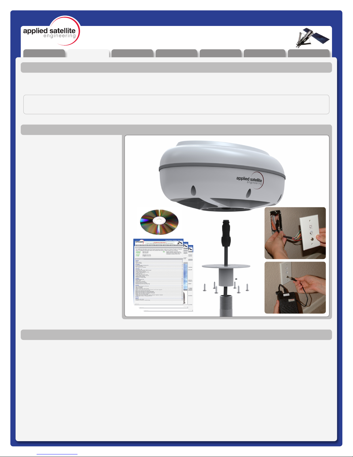
What’s Inside the Box
IMPORTANT:
The ASE ComCenter ‘Outdoor’ does NOT include the mounting pole, as the length of this component will vary widely.
For this installation you will need a safe work area that is outdoors with a 360 degree view of the sky (for device testing
along with a few tools including a #2 Phillips screwdriver, a 2mm Allen Wrench, and possibly a stable Ladder.
Tools Required for Installation
A ComCenter IIG / Outdoor Unit
B Communications Cable
C Universal Wallplate
D AC/DC power adapter: Universal
AC input / 24VDC, 15W output
E Pole Mount Adapter &
Hardware
F Installation CD
G Product Manual
* 20 Foot Interface Cable
with cable to connector
breakout (RJ-11, RJ-45,
Power)
* Item not shown in Illustration
Optional 50 to 100 foot
extensions allow up
to 400 foot lengths
A
C
D
B
E
F
G
Unpacking Preparation Installation Warranty
Operation
AppendixOverview
REV-3.0 [3-17-11] 7
ComCenter-II ‘Outdoor’ Product Manual
Pre-Use Testing of Components and Connectivity
Before spending the time to fully install the Comcenter in its new home, its best to test the components and
connectivity while all of the parts are still easily accessible.
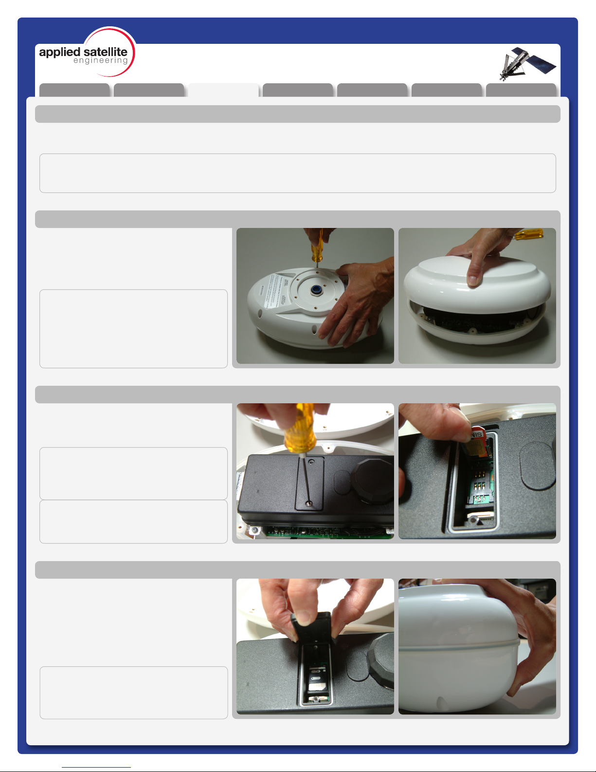
Preparation
Open the Top cover from the ComCenter by
removing the screws in the body as shown.
Lightly squeezing the top shell will break the
seal with the waterproof gasket and allow
access to the interior.
Accessing Internal SIM Slot
Remove the SIM door using a screwdriver;
and then place the unlocked SIM card into
the slot as shown.
Installing SIM Card
Once the SIM card has been installed, close
the SIM door and lock it with the provided
screws. Next re-attach the top shell taking
care that the waterproof gasket seals
properly as shown. Screw down the casing
fasteners only once the gasket is properly
seated.
Re-Assembling ComCenter Casing
IMPORTANT:
Be sure that the rubber seal is properly
seated before re-tightening the Casing
Screws.
NOTE:
This device will be shipped to the distribu-
tor WITHOUT the screws installed. The
screws can be found inside a plastic bag.
After installing the SIM card, it is very im-
portant that the screws are located and
installed.
IMPORTANT:
THE FOLLOWING STEPS ARE NOT TYPICALLY AN END USER REQUIREMENT, THE SIM CARD SHOULD BE
PRE-CONFIGURED (UNLOCKED) AND INSTALLED BY YOUR SERVICE PROVIDER.
IMPORTANT:
Make sure to “lock” the SIM holder by
gently pushing it in the direction indicated
by the arrow.
IMPORTANT:
The modem in your ComCenter may not
be identical to that pictured here
Unpacking Preparation Installation Warranty
Operation
AppendixOverview
REV-3.0 [3-17-11] 8
ComCenter-II ‘Outdoor’ Product Manual
The next step in the Pre-Use Test Process will be to connect the power and at least one telephone handset. This will allow
you to double check that the unit, and your cables, will perform properly once fully installed.
Pre-Use Testing of Components and Connectivity (Continued)
Preparation
To properly test the system, you’ll need to
place the antenna unit in a position with a
360 degree view of the sky. Any obstructions
will cause a lapse in connectivity between
the ComCenter and the orbiting satellites.
Run the cable to the supplied adapter (see
below)
Locating Satellite-Viewable Work Area
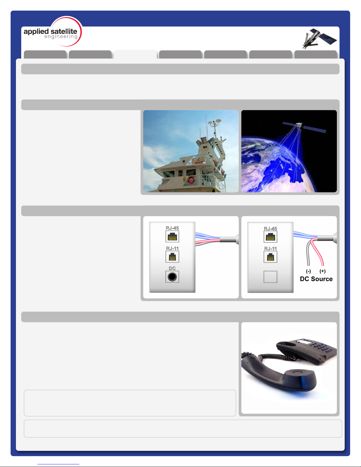
If you intend to use the supplied power
transformer, then connect the power jack the
wall plate as shown in the top illustration. If
you prefer to connect the system to another
DC power source*, then simply separate the
wires as shown in the bottom illustration and
connect those to the alternate source.
Next connect a standard analog/POTS
telephone into the RJ11 jack.
*24 - 36VDC, 15 Watts
Attaching Phone and Power
Once the initialization has completed (about 30 seconds), you should hear one of
the following tone patterns (depending on your system settings).
[Long] (Constant Dialtone) [Found Home Network]
or
[Pause]-[Short]-[Pause]........ [Waiting for PIN code]
This indicates that all elements of the system are operating properly If any element
of the system is not operating correctly, the earpiece will emit a ‘fault code’.. Refer
to Appendix A for code denitions and the troubleshooting steps to resolve them.
Activating and Testing the System
NOTE:
At this point, you should be able to pick up the Handset and hear a tone
pattern. If not, you should check all your connections and try again.
IMPORTANT:
For a complete listing of the meaning behind system tone messages, see Appendix A.
Unpacking Preparation Installation Warranty
Operation
AppendixOverview
REV-3.0 [3-17-11] 9
ComCenter-II ‘Outdoor’ Product Manual
Installation
Installation
Once you have successfully “Pre-Use” tested the ComCenter device, you will be ready to proceed with system
instalation. Step-by-Step illustrations for this process are provided below.
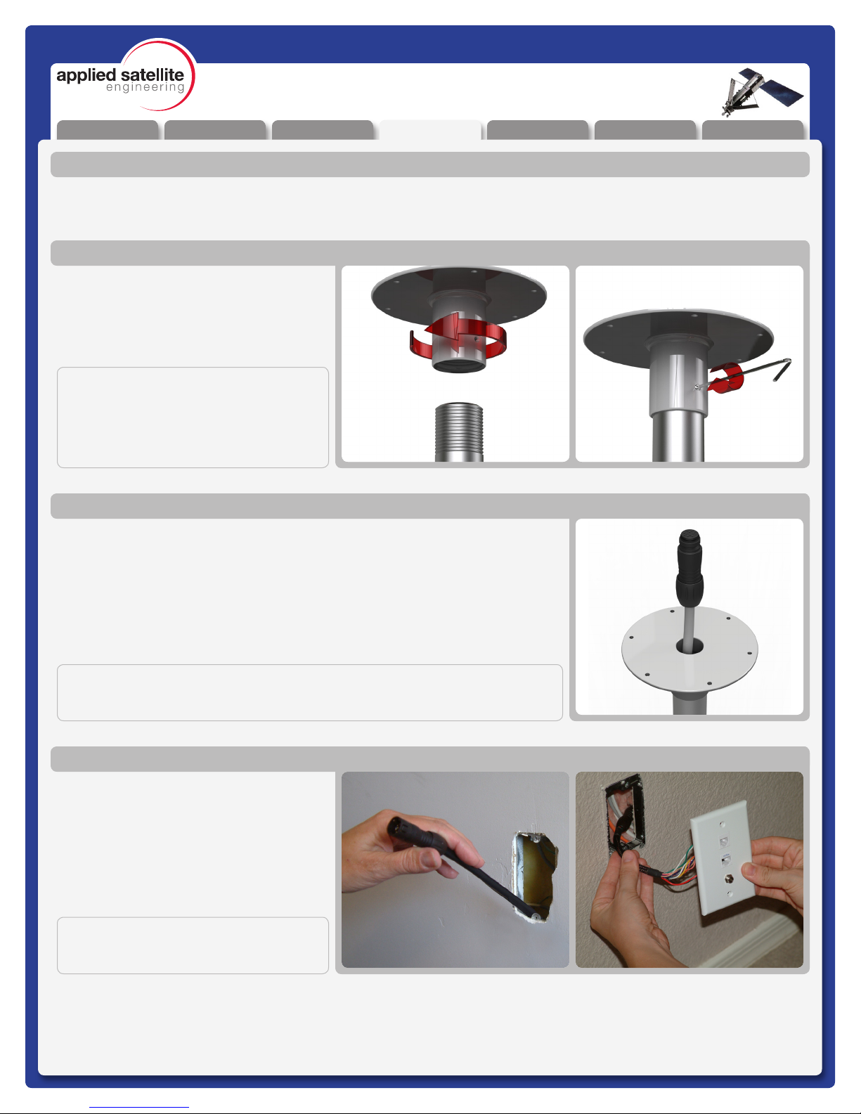
Attach the ComCenter mounting bracket to
the top of a Threaded 1” diameter pipe by
spinning the bracket clockwise. Once the
bracket no longer turns freely, lock it in place
using the set-screw as shown.
Attaching Bracket to Pole
Feed the Communications cable down the bracket (and pipe) toward your
designated communications area. It is important to leave yourself 6-8” of extra
cable that will serve as a service loop while attaching the ComCenter Outdoor
Unit.
Routing Cables
Pull the opposite end of the communications
cable through the wall and attach it to the
supplied wall-plate adapter. Next attach the
wall-plate to the wall as shown.
Connecting the ComCenter
NOTE:
Usable Mounting Poles measure 1” in
Diameter and are end-threaded with
a 14 thread-per-inch thread.
IMPORTANT:
Be sure the exposed cable contains the “Female” connector, and not the “Male”.
IMPORTANT:
Be sure the exposed cable contains the
“Male” connector, and not the “Female”.
Unpacking Preparation Installation Warranty
Operation
AppendixOverview
REV-3.0 [3-17-11] 10
ComCenter-II ‘Outdoor’ Product Manual
Installation
Installation (continued)
The next steps in the installation process involve making all of the nal cable connections and mounting the
ComCenter Outdoor Device to the newly assembled mounting bracket.
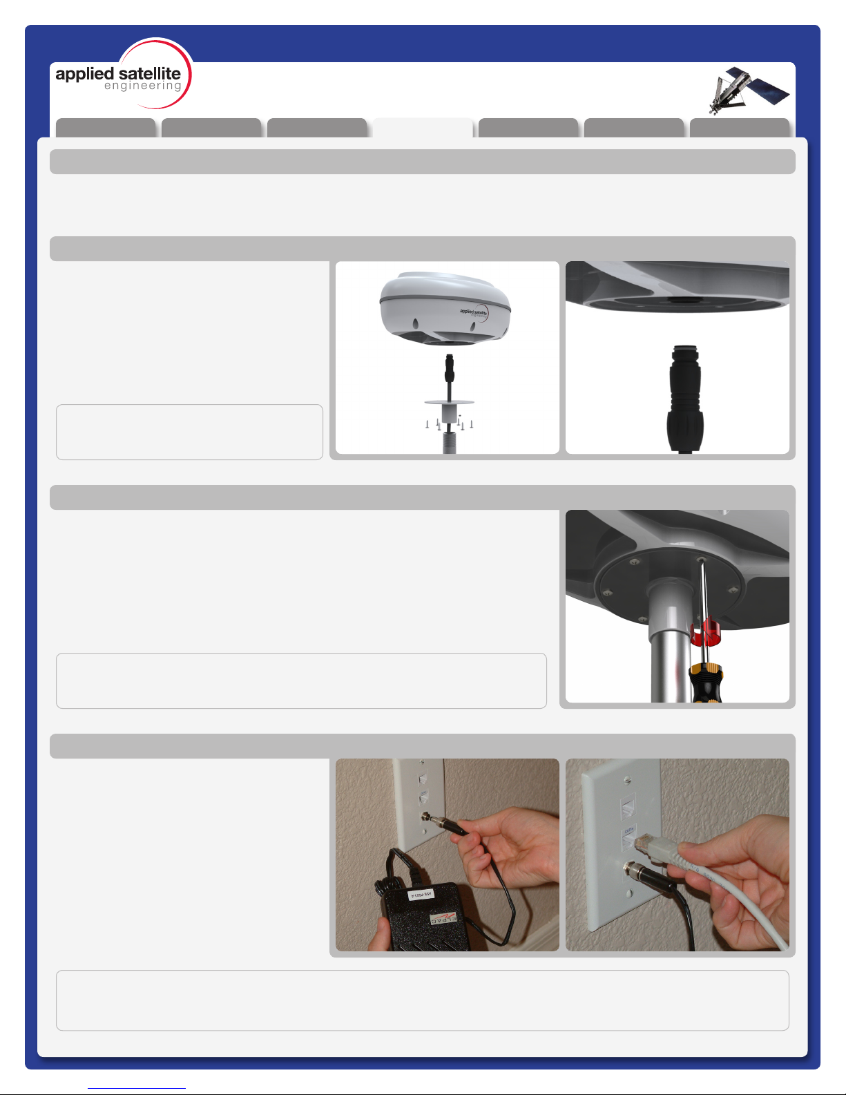
Plug the Female end of the communications
cable to the underside of the ComCenter
Outdoor unit. The cable is “keyed” to allow
proper pin alignment, gently rotate the plug
until it slides into place with a tactile “click”.
Attaching Cable to ComCenter
Once aligned, tighten the mounting screws in the bracket to the underside of the
ComCenter Outdoor Unit.
Attaching ComCenter to Bracket
Now that the device is fully installed, plug
in the standard telephone handset, the
CAT-5 Communications Cable, and nally
the power Supply Cable as shown. Conrm
(again) proper connectivity by listening for
the tone patterns in the handset.
If you do NOT have a steady dial tone, you
should rst check all of your connections
and try again.
Attaching Power and Phones to Wall Plate
NOTE:
At this point, you should be able to pick up the Handset and hear a steady Dial Tone. If not, see troubleshooting
in Appendix A
IMPORTANT:
Be careful not to bend pins.
IMPORTANT:
The ComCenter Outdoor must be installed and oriented horizontally as shown
for proper satellite visibility.
This manual suits for next models
1
Table of contents
Other Applied Satellite Engineering Antenna manuals

Popular Antenna manuals by other brands

Alfa Network
Alfa Network APA-L01 Specifications

Naval
Naval PR-422CA Operation manual

Feig Electronic
Feig Electronic ID ISC.ANTH200/200 Series manual

TERK Technologies
TERK Technologies TV44 owner's manual

Directive Systems & Engineering
Directive Systems & Engineering DSE2324LYRMK quick start guide

HP
HP J8999A instructions


CommScope
CommScope CMAX-OMFX-43M-I53 Installation instruction

Ramsey Electronics
Ramsey Electronics DAP25 Kit assembly and instruction manual

COBHAM
COBHAM SAILOR 800 VSAT Replacement procedure

Trango Systems
Trango Systems AD900-9 Specification sheet

Steren
Steren ANT-100 user manual

Proxim
Proxim 5054-PA-23 quick start guide