AGA 6-4 Series User manual

AGA SIX-FOUR SERIES - DC6 (FFD)
(NATURAL GAS AND PROPANE GAS)
OWNERS MANUAL
03/08 EINS 514735
PLEASE READ THESE INSTRUCTIONS BEFORE USING THIS APPLIANCE
INSTALLER: LEAVE THESE INSTRUCTIONS WITH THE APPLIANCE
CUSTOMER: KEEP THESE INSTRUCTIONS FOR FUTURE REFERENCE
Remember, when replacing a part on this appliance, use only spare parts that you can be
assured conform to the safety and performance specification that we require. Do not use
reconditioned or copy parts that have not been clearly authorised by AGA.
Comprising
Servicing, Installation & Users
Instructions
&
Cooking Guide
For use in USA/Canada
Do not store or use gasoline or other flammable vapors and liquids in the vicinity
of this or any other appliance.
WHAT DO YOU DO IF YOU SMELL GAS
. Do not try to light any appliance.
. Do not touch any electrical switch
. Do not use any phone in your building.
. Immediately call your gas supplier from a neighbors phone.
Follow the gas suppliers instructions
. If you can not reach your gas supplier call the fire department.
Installation and service must be performed by a qualified installer, service
agency or the gas supplier.
WARNING: If the information in this manual is not followed exactly, a fire or
explosion may result causing property damage,personal injury or death.
SECTION PAGE
INSTALLATION SECTION 3
TECHNICAL DATA 4
INSTALLATION 5
FITTING AND PRODUCT DIMENSIONS 6
ELECTRICAL CONNECTION 7 - 8
CONNECTING TO GAS 9
LOCATION 10
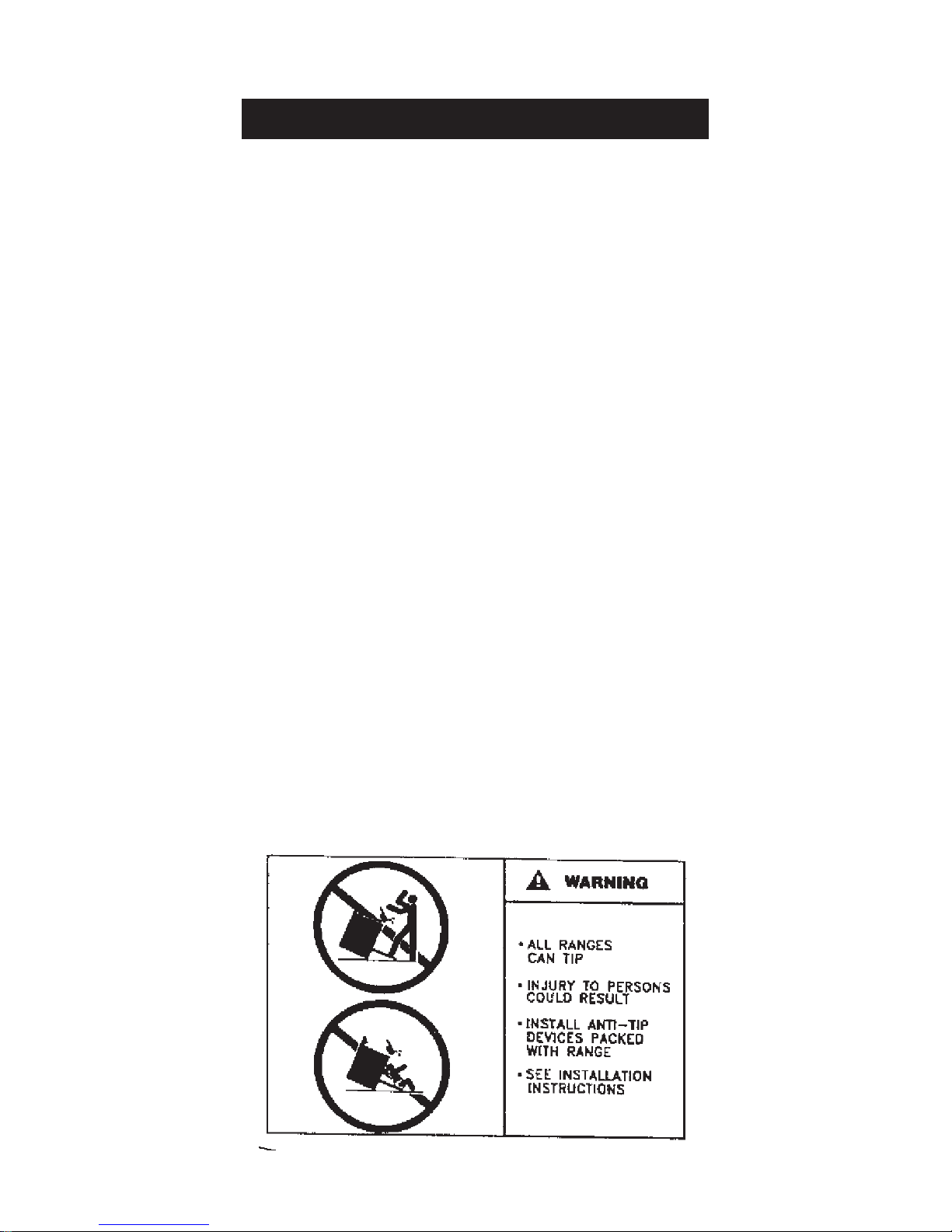
COOKER STABILITY 11 - 12
PRESSURE TESTING 12
LEVELLING AND MOBILITY WHEELS 13
FITTING OF HOTPLATE CASTINGS AND PAN 14 - 17
SUPPORTS
SPLASHBACK 18
USERS GUIDE 19
GENERAL INFORMATION 20
SAFETY PRECAUTIONS AND HINTS 21
PRODUCT VIEW 22
CONTROL PANEL 23
GAS HOTPLATE 24 - 25
TO FIT PAN SUPPORTS 26
SETTING UP THE COOKER FOR USE 27
SIMMERING OVEN 28
SIMMERING OVEN RECIPES 29 - 32
THE BROILER 33
THE OVENS 34
OVEN COOKING GUIDE 35 - 39
THE MINUTE TIMER 40
AUTOMATIC COOKING CONTROL 41 - 42
CLEANING AND CARING FOR YOUR COOKER 42 - 48
SERVICING SECTION 49
SERVICING 50 - 58
2
CONTENTS

Installation
Section
3
Remember, when replacing a part on this appliance, use only spare parts that you can be
assured conform to the safety and performance specification that we require. Do not use
reconditioned or copy parts that have not been clearly authorised by AGA.
CAUTION:
THIS UNIT IS HEAVY, PROPER EQUIPMENT AND ADEQUATE
MANPOWER MUST BE USED IN MOVING THE RANGE TO
AVOID DAMAGE TO THE UNIT OR THE FLOOR

HOTPLATE
NATURAL GAS L.H.F. R.H.F. R.H.R. L.H.R. CENTRE CENTRE
WOK FRONT REAR
BURNER TYPE ULTRA-RAPID RAPID RAPID SEMI-RAPID SEMI-RAPID ULTRA-RAPID
MAXIMUM HEAT 4.5 kW 3.22 kW 3.22 kW 1.91 kW 1.91 kW 5.1 kW
INPUT
BTU’s/hr 15,350 11,000 11,000 6,500 6,500 17,400
INJECTOR MARKING
MAIN 80Hi 155 155 118 118 200
SECONDARY 2 x 1.30 - - - - -
PRESSURE POINT POSITION:REAR RH SIDE OF HOTPLATE
PRESSURE SETTING: 4” W.G.
BURNER IGNITION: H.T. SPARK
PROPANE L.H.F. R.H.F. R.H.R. L.H.R. CENTRE CENTRE
WOK FRONT REAR
BURNER TYPE ULTRA-RAPIDRAPID RAPID SEMI-RAPID SEMI-RAPID ULTRA-RAPID
MAXIMUM HEAT 4.2 kW 3.0 kW 3.0 kW 1.75 kW 1.75 kW 4.5 kW
INPUT
BTU’s/hr 14,330 10,250 10,250 6000 6000 15,350
INJECTOR MARKING
MAIN 46 85 85 65 65 110
SECONDARY 2 x 66 - - - - -
PRESSURE POINT POSITION:REAR RH SIDE OF HOTPLATE
PRESSURE SETTING: 10” W.G.
BURNER IGNITION: H.T. SPARK
ELECTRIC GRILL AND OVENS WEIGHT OF APPLIANCE: 220 kg
TOP OVEN POWER RATING - 1.45 kW
BROILER ELEMENT - POWER RATING 2.45 kW
SLOW COOKING OVEN - POWER RATING 1.0 kW
LOWER OVEN (FAN) - 2.2 kW
240 VOLT 60 Hz SINGLE PHASE
The data plaque is located on a pull out plate - lower front of appliance (See Fig. 10, Page 22).
TYPICAL SECTION VIEW OF FLAMES:
TECHNICAL DATA
4
15/16”
9/16”
7/8”
1/2”
3/4”
9/16”
LHF HOTPLATE BURNER
CR HOTPLATE BURNER
RHF & RHR HOTPLATE
BURNER LHR & CF HOTPLATE BURNER

CAUTION: THIS INSTALLATION MUST CONFORM WITH LOCAL CODES OR, IN THE
ABSENCE OF LOCAL CODES WITH THE NATIONAL FUEL GAS CODE, ANSI Z223.I/NFPA
54 AND NATIONAL ELECTRICAL CODE ANSI/NFPA 70 (IN CANADA CAN/CGA-B149) AND
ONLY USED IN A WELL VENTILATED SPACE, READ THESE INSTRUCTIONS BEFORE
INSTALLING OR USING THIS APPLIANCE.
PRIOR TO INSTALLATION, ENSURE THAT THE LOCAL DISTRIBUTION CONDITIONS
(NATURE OF GAS AND GAS PRESSURE) AND THE ADJUSTMENTS OF THE APPLIANCE
ARE COMPATIBLE.
THE GAS ADJUSTMENT CONDITIONS FOR THIS APPLIANCE ARE STATED ON THE DATA
PLATE WHICH IS SITUATED IN THE CENTRE VENT SLOT NEAR THE BASE OF THE
FRONT PLATE.
This appliance is not connected to a combustion products evacuation device. it shall be installed
and connected in accordance with current installation regulations. Particular attention shall be
given to the relevant requirements regarding ventilation.
It should be in accordance with any relevant requirements of the Gas Region and LocalAuthority.
The appliance must be disconnected from the gas supply piping system during any pressure
testing of that system test pressure in excess of 1/2 psi (3.5 kPa).
The appliance must be isolated from the gas supply piping system by closing its individual
manual shut off valve during any pressure testing of the gas supply system at test pressures
equal to or less than 1/2 psi (3.5 kPa).
On completion, test the gas installation for soundness and purge. Leak testing of the appliance
shall be conducted according to the manufacturer’s instructions.
NOTE: Use soapy water solution on new gas connections to ensure there are no gas leaks.
WARNING: ELECTRIC SHOCK HAZARD
It is the customers responsibility to contact a qualified electrical installer to make sure the
electrical installation is adequate and in conformance with National Electrical Code ANSI/FPA
70-latest edition, and all local codes and ordinances.
Take special care when cutting holes in walls or floor. Electrical wires may be behind the wall or
floor covering and could cause an electrical shock if you touch them.
Locate any electrical circuits that could be affected by the installation of this product and
disconnect power circuit.
Electrical ground is required on this appliance.
Do not have a fuse in the neutral or grounding circuit. A fuse in the neutral or grounding circuit
could result in electrical shock.
Do not use an extension cord with this appliance.
Check with a qualified electrician if you are not sure the appliance is properly grounded.
Failure to follow these instructions could result in death or serious injury.
INSTALLATION
5

FITTING AND PRODUCT DIMENSIONS
6
Fig. 1 DESN 512636 C
Any side wall above the cooker on either side shall be not less than 3” (75mm) horizontally from
the cooker (Fig. 1).
Combustible surfaces over the top of the cooker must not be closer than 28” (711mm) and must
not exceed 13” (400mm) in depth.
0” clearance to the back of the stove may be obtained when installing the appliance against a
non-combustible wall or if the wall behind the stove is deemed combustible, then the minimum
spacing from the back of the stove to nearest combustible wall is 6”.
A minimum clearance of 39 1/2” (1000mm) must be available at the front of the cooker to enable
it to be serviced.
Any opening in the wall behind the appliance and in the floor under the appliance shall be sealed.
The cooker must stand on a firm and level surface, we recommend that any soft material such
as linoleum is removed.
The vent slots in the back of the top plate must not be obstructed.

Electric Shock Hazard
Electrical Grounding is required on this appliance.
Do Not connect to the electrical supply until the appliance is permanently grounded.
Disconnect the power to the junction box before making the electrical connection.
This appliance must be connected to a grounded, metallic, permanent supply or a
grounding connector should be connected to the grounding terminal or wire lead on the
appliance.
Do Not ground to gas pipe. Failure to follow these instructions could result in death or
serious injury.
zA four-wire single phase 240-volt, 60-Hz, AC-only electrical supply is required on a
separate circuit, fused on both sides of the line.
zA time-delay fuse or circuit breaker is recommended.
zIf local codes permit, use a U.L. listed, 250-volt, 30-amperes power cord (pigtail). This cord
contains four No. 10 copper wires and matches a four-wire receptacle of type 14-30R.
Connectors on the appliance end must be provided at the point the power supply enters
the appliance.
Wires sizes (COPPER WIRE ONLY) and connections must conform with the rating of range
(30-amperes).
zThe wiring diagram is located on the back of the appliance.
THIS APPLIANCE MUST HAVE THE FACILITY OF BEING COMPLETELY ISOLATED
FROM THE ELECTRICITY SUPPLY.
THE APPLIANCE MUST BE COMPLETELY ISOLATED FROM THE ELECTRICITY
SUPPLY BEFORE SERVICING.
7
ELECTRICAL CONNECTION

ELECTRICAL CONNECTION IS LOCATED AT THE TOP RIGHT HAND SIDE OF THE
APPLIANCE, BEHIND SIDE PANEL. DURING INSTALLATION REMOVE THE RIGHT HAND
SIDE PANEL TO CONNECT ELECTRICAL SUPPLY.
Remove 6 screws securing side panel to gain access to mains terminal. See Fig. 3 for location
of cover.
Remember that the mains electrical cable must be routed through the grommet at the rear right
hand side of the cooker near the top via a UL listed strain relief bracket, before connecting to the
mains terminal connection.
REFER TO FIG. 2 & 2A for wire connection to appliance.
Remember that an excess of cable length is required inside the cooker to allow for possible
servicing of the spark generator, there should be at least 31” (0.78m) of cable from the appliance.
Remember that an excess of cable length is required behind the cooker for the withdrawal of the
cooker from between the kitchen units etc.
Replace the right hand side panel once electrical connection has been made and replace fixing
screws.
NOTE: Ensure the insulation card covering the mains terminal is in place, between the side
panel and mains terminal.
ELECTRICAL CONNECTION (continued)
Fig. 2
Fig. 2A
DESN 514739
DESN 512951
8

WIRING DIAGRAM 59
CAUTION: ENSURE THAT THE COOKER IS ISOLATED FROM ELECTRIC SUPPLY
The cooker can be installed with an approved flexible connection. Supply piping should not be
less than 3/8 I/D Flexiline. Connection is made to the 1/2” NPT female thread located just below
the hotplate level on the right hand side of the cooker.
The gas flexiline connector must be fitted in the shaded area dimensioned in Fig. 3. Take into
account that it must be possible to pull the cooker forward sufficiently for servicing. Ensure
flexiline hose is not trapped between cooker back panel and rear wall. Ensure hose is routed
within the shaded area and away from shielded oven vents.
NOTE: Use soapy water solution on new gas connections to ensure there are no gas leaks.
NOTE: AN EASILY ACCESSIBLE MANUAL SHUT GAS VALVE MUST BE FITTED BEFORE
THE METAL FLEX GAS LINE.
Check for gas soundness after connecting the appliance.
9
CONNECTING TO GAS
Fig. 3 DESN 512639 B

This appliance must be installed on 1/8” thick Commercial Grade Vinyl composition floor finishing
materials or equivalent.
Combustible side wall clearance above the hotplate shall be greater than 3”.
Surfaces over the top of the range must not be closer than 28” and must not exceed 13” in depth.
The vent slots in the back of the top plate (or shroud) must not be obstructed.
Note: It is essential that the supply cable is routed away from any hot surfaces i.e. hot flue pipes.
In the interests of safety, due consideration must be given to the protection of the electric cable
to the unit.
Remember than an excess of cable length is required for the possible withdrawal of the range.
A electrical socket type 14-30R must be provided within 5 feet of the left hand side of the range
and be accessible for disconnection.
THE INSTALLATION MUST CONFORM WITH THE NATIONAL ELECTRIC CODE.
Disconnect the electrical supply before servicing the appliance. Electrical hook-up must be done
by a licenced electrician.
An easily accessible manual shut off gas valve must be fitted before the metal flexi gas line
supply to the range. DO NOT fit valve behind the range.
Any opening in the wall behind the appliance and in the floor under the appliance must be
sealed.
If the range must be installed beside a refrigerator, it is important for proper air circulation that
there be at least 5” (175mm) of space between the two appliances.
LOCATION
10
This manual suits for next models
5
Table of contents
Other AGA Kitchen Appliance manuals


AGA
AGA COOKMASTER R40G User manual

AGA
AGA 100/3 Instruction Manual

AGA
AGA AIMS EC User manual

AGA
AGA exclusive User manual

AGA
AGA eR3 110-4 Instruction Manual

AGA
AGA Fusion User manual

AGA
AGA PROFESSIONAL 110 Gas Instruction Manual

AGA
AGA APRO6BARM User manual

AGA
AGA OC Instruction Manual

AGA
AGA APRO30DFSS User manual


Popular Kitchen Appliance manuals by other brands

Tayama
Tayama TYG-35AF instruction manual

AEG
AEG 43172V-MN user manual

REBER
REBER Professional 40 Use and maintenance

North American
North American BB12482G / TR-F-04-B-NCT-1 Assembly and operating instructions

Presto
Presto fountain popper instruction manual

Westmark
Westmark 1035 2260 operating instructions


